Choosing an Adder
Over the last four articles we built three adders. Each is a different way of dealing with the same carry chain, each has its own costs, and each is the right answer in some context. This article is about making that choice deliberately. I line them up on delay, area and power, introduce the prefix adders that real processors use, and then look at the practical split between FPGA and ASIC, which changes the answer more than anything else.
The architectures side by side
| Adder | Delay | Area | Power | Typical use |
|---|---|---|---|---|
| Ripple-carry | $O(N)$ | $O(N)$ | low | narrow widths, area-constrained, FPGA carry chains |
| Carry-skip | $O(\sqrt{N})$ | $O(N)$ | low to medium | moderate speed at little extra area |
| Carry-select | $O(\sqrt{N})$ | about $1.7 \times O(N)$ | medium | a good balance, simple to lay out |
| Carry-lookahead | $O(\log N)$ | $O(N \log N)$ | high | fast ASIC datapaths |
| Kogge-Stone prefix | $O(\log N)$ | $O(N \log N)$ | highest | maximum speed, processor ALUs |
| Brent-Kung prefix | $O(\log N)$ | $O(N)$ | high | $O(\log N)$ delay at lower area |
The delay column gives the scaling, and scaling only matters for large $N$. At four bits every architecture in the table is about the same speed; the differences between $N$, $\sqrt{N}$ and $\log N$ only open up from 16 bits or so. Never choose on scaling alone. Put the numbers in.
Prefix adders
The carry-lookahead adder computes carries with two-level AND-OR logic whose terms grow with width, which is the fan-in problem from two articles ago. Prefix adders solve this more neatly by arranging the generate and propagate combination as a tree.
The operation at each node combines two adjacent spans of bits. Given $(G_{hi}, P_{hi})$ for the upper span and $(G_{lo}, P_{lo})$ for the lower:
$$G = G_{hi} + P_{hi} G_{lo} \qquad P = P_{hi} P_{lo}$$
This is exactly the group generate and propagate from the hierarchical CLA. A prefix adder applies it in a regular tree so that the depth is $\log_2 N$ and every node has a fan-in of two.
Kogge-Stone is the fastest and most common. It has $\log_2 N$ levels with $N$ nodes in each, and after the last level every bit position has the combined $G$ and $P$ of all the bits below it, which is its carry. For 64 bits that is 6 levels plus one for the initial $G$ and $P$ and one for the sum XOR, about 8 gate delays. The area is $O(N \log N)$, roughly 384 combine nodes for 64 bits, and the wiring is dense.
Brent-Kung is a sparser tree that combines only alternate nodes at each level and then distributes the results in a second pass. The node count drops to $O(N)$ and the depth rises to about $2\log_2 N - 1$. It is the choice when $\log N$ delay is needed but the area of Kogge-Stone is not affordable.
Han-Carlson and similar hybrids sit in between, using a Kogge-Stone tree on half the bits and a final ripple for the rest.
Prefix adders are what the integer datapaths of production processors use. When you read that a processor does a 64-bit add in one cycle at 5 GHz, a prefix tree is doing it.
Delay against area
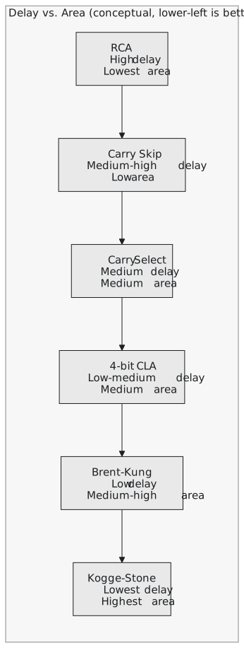
Figure 1 plots the architectures on delay against area. Nothing sits in the corner with both minimum delay and minimum area; every speed-up costs area and, usually, power. The designer’s job is to find the point on that frontier that fits the constraints.
FPGA against ASIC
This is the most practically important point in the section, and it is the one people arriving from theory most often miss.
On an ASIC, delay comes from the standard cells and wiring, and the synthesis tool chooses an adder structure to meet your timing constraint: a small ripple-carry adder if it can, a CLA or prefix adder if it must.
On an FPGA the situation is different. Xilinx, Intel and Lattice devices all have dedicated carry chains: routing between adjacent logic slices that carries the carry signal without passing through a lookup table. The delay per bit on that chain is around 30 to 50 ps on a modern device, against a few hundred picoseconds for a signal that goes through a LUT.
That changes the comparison completely. A 16-bit ripple-carry adder on the carry chain is roughly $16 \times 40 = 640$ ps. A 16-bit CLA built from LUTs is about 8 levels at perhaps 200 ps each, 1.6 ns. The ripple-carry adder wins, uses fewer LUTs, and routes predictably.
So on an FPGA: write A + B and let the synthesizer infer the carry chain. Do not build a CLA or carry-select adder by hand. It will use more LUTs and be slower. Look in the utilisation report for CARRY4 or CARRY8 primitives to confirm the chain was used.
On an ASIC it is the other way round. The tool given A + B and a timing constraint will pick a fast structure when the constraint demands it, and a small one when it does not.
What the synthesis tool does
The usual flow is: write assign sum = a + b;, give timing constraints in an SDC file, run synthesis, and let the tool choose an adder from its library to meet the constraint. You then check the timing report to see whether the critical path meets the clock. For example:
# Require the path into the sum register to close in 2.0 ns
set_max_delay 2.0 -to [get_pins adder_inst/sum_reg*/D]
Given that constraint in a 28 nm library, the tool will pick a CLA or prefix structure rather than ripple-carry.
You still need to understand the architectures, for three reasons. First, to constrain the tool sensibly: if you need a 32-bit adder at 500 MHz on 28 nm, you have about 2 ns, or roughly 40 gate delays at 50 ps, and a ripple-carry adder needs 66, so the constraint has to be tight enough to force a faster structure. Second, to read the timing report when it fails: recognising a carry chain in the critical path tells you immediately what to change. Third, for the unusual cases, irregular widths, operands with known constant bits, designs where power matters more than speed, where the tool’s default is not the best and you have to steer it.
A worked design
Specification. A 32-bit adder for a 28 nm ASIC at 500 MHz. Gate delay 50 ps.
Budget. The period is 2 ns. Allow 50 ps for setup and 100 ps for clock skew, leaving 1.85 ns, or 37 gate delays.
| Architecture | 32-bit gate delays | Time | Meets timing |
|---|---|---|---|
| Ripple-carry | 66 | 3.3 ns | no |
| Carry-skip, optimal groups | about 14 | 0.70 ns | yes |
| Carry-select, 4-bit groups | 19 | 0.95 ns | yes |
| Hierarchical CLA | about 10 | 0.50 ns | yes |
| Kogge-Stone | about 7 | 0.35 ns | yes |
Carry-skip meets timing with 23 gate delays to spare at the smallest area. Kogge-Stone has 30 to spare at the largest. A hierarchical CLA in the middle is a reasonable choice, and it is roughly what the tool will produce for a 2 ns constraint.
Notice that slack is a resource. Twenty-odd gate delays of unused margin can be spent as lower supply voltage for power, as a smaller adder for area, or as headroom to run faster later. Knowing the architectures lets you decide which, instead of accepting whatever the tool gave you.
In short
Use a ripple-carry adder for eight bits or fewer, or whenever you are on an FPGA, or when the clock is slow and area is what matters.
Use carry-skip for a moderate speed-up at little extra area on an ASIC.
Use carry-select for a simple, regular square-root adder at 16 to 64 bits when the area is acceptable.
Use a hierarchical CLA for $\log N$ delay at 16 to 64 bits with standard cells.
Use Kogge-Stone or Brent-Kung when speed is the primary constraint and area is available.
On any FPGA, write A + B and check for the carry-chain primitives in the report.
Practice Exercise
An ALU for a wearable device needs a 16-bit adder. Battery life is critical and the clock is 100 MHz. The gate delay is 100 ps, setup is 100 ps and skew is 50 ps. What is the timing budget? Does a ripple-carry adder meet it? Which adder would you use? Would the answer change on an FPGA?
Solution
The period is 10 ns; less setup and skew leaves 9.85 ns, about 98 gate delays.
A 16-bit ripple-carry adder is 34 gate delays, 3.4 ns, well within budget with 6.45 ns to spare.
Use the ripple-carry adder. It is the smallest and, because nothing is computed speculatively, the lowest-power option. A faster adder would spend area and power to shorten a path that is already short enough.
On an FPGA the recommendation is the same, write A + B and let the tool use the carry chain, but for a different reason: there the carry chain is the fastest option at any clock rate, not just this one.
You can now add $N$-bit numbers as fast as the design requires. In the next section we get subtraction, which in two’s complement is one small change to the adder, and from there build the complete ALU.