The Wallace Tree
The array multiplier of the last article adds its partial products in a strict order: row 1 waits for row 0, row 2 waits for row 1, and every adder sits idle until the one above it finishes. For 32-bit operands that is around thirty adder rows in sequence. In 1964 Christopher Wallace asked why the rows had to be added in order at all. Nothing in the silicon cares which row a bit belongs to. He found that a simple circuit can take three rows and turn them into two, at every bit position at once, and that repeating this collapses the rows in a tree whose depth grows only as the logarithm of the width. That is the Wallace tree, and every fast multiplier since, in every integer unit, floating-point unit and DSP, is built on it.
The carry-save adder
The building block is the carry-save adder (CSA). It takes three $N$-bit inputs $A$, $B$, $C$ and produces two $N$-bit outputs, a sum vector and a carry vector, and the important thing is what it does not do: it does not propagate carries between bit positions. Each position is an independent full adder.
$$S_i = A_i \oplus B_i \oplus C_i$$
$$C_{i+1} = A_iB_i + B_iC_i + A_iC_i$$
The carry from position $i$ is written into position $i + 1$ of the carry vector, as data, and is not consumed by position $i + 1$ within this adder. Because nothing ripples, a CSA takes two gate delays whatever its width. A 4-bit CSA and a 64-bit CSA have the same delay.
The two outputs together represent the same number as $A + B + C$, in a split form. To get the actual number you eventually have to add the sum and carry vectors with an ordinary adder, but you can postpone that as long as you like. Figure 1 shows the structure.
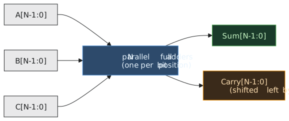
A CSA is architecturally trivial, just $N$ full adders side by side. The idea is in how it is used: by refusing to resolve the carry, it keeps the running total in a two-vector form that can feed straight into the next CSA without waiting.
Four partial products
A 4×4 multiplier has four partial product rows, PP0 to PP3. The array adds them as $((PP0 + PP1) + PP2) + PP3$, three adders in sequence. The Wallace tree does this instead (Figure 2):
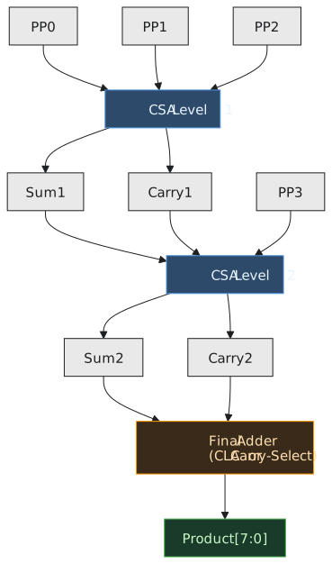
Level 1: a CSA takes PP0, PP1 and PP2 and produces a sum and a carry vector. PP3 passes through. Four rows have become three.
Level 2: a CSA takes the sum, the carry and PP3 and produces a new sum and carry. Three rows have become two.
Final adder: a fast adder, typically carry-lookahead, adds the last two vectors to give the product.
Each level turns three rows into two, so the row count shrinks by about a factor of 1.5 per level and the number of levels grows as the logarithm of $N$. In practice the counts are: 3 rows need 1 level, 4 need 2, 6 need 3, 9 need 4, 13 need 5, 19 need 6, 28 need 7 and 42 need 8, so 32 partial products need 8 levels.
Tracing 0110 × 0101
The partial products, aligned to 8 bits: PP0 = 00000110, PP1 = 00000000, PP2 = 00011000, PP3 = 00000000.
Level 1, on PP0, PP1 and PP2, bit by bit. At each position at most one input is 1, so every sum bit is just that input and every carry is 0: sum = 00011110, carry = 00000000.
Level 2, on the sum, the carry and PP3: again only one non-zero input, so sum = 00011110, carry = 00000000.
Final adder: $00011110 + 00000000 = 00011110 = 30$.
This example is too easy to show the carries doing anything, so try $1111 \times 1111$ for yourself; the carry vectors fill up and the final adder does real work.
A mistake to watch for: the carry vector out of a CSA belongs one position to the left. If you feed it into the next level without that shift, the result is wrong by a factor of two in the carry part, and it looks plausible.
Timing
| Part | Delay |
|---|---|
| AND array | 1 |
| each CSA level | 2 |
| final adder, carry-lookahead, $2N$ bits | about 4 to 10 depending on width |
| Width | Partial products | CSA levels | Wallace, approx. | Array, approx. |
|---|---|---|---|---|
| 4 | 4 | 2 | 9 | 10 |
| 8 | 8 | 4 | 15 | 22 |
| 16 | 16 | 6 | 21 | 42 |
| 32 | 32 | 8 | 27 | 82 |
At four bits there is nothing in it. At 32 bits the Wallace tree is three times faster, and the ratio keeps growing.
The Dadda variant
Luigi Dadda published a refinement in 1965 that aims at minimum hardware rather than maximum reduction at each step. A Wallace tree reduces as aggressively as it can at every level. A Dadda tree reduces each level only as far as necessary to finish in the same number of levels, which lets it use fewer full and half adders, typically 10 to 20 percent fewer, for the same depth. The structure is more irregular, but synthesis tools do not mind; in an ASIC flow the tool builds the reduction tree directly from the timing and area constraints and the Wallace/Dadda distinction blurs.
The double-precision multiplier in a floating-point unit reduces 53 partial product rows with exactly this technique, then finishes with a fast adder. It is the same circuit as the 4×4 tree here, scaled up.
Costs
The Wallace tree is faster than the array, and it pays for that in three ways. The wiring is irregular, because carry vectors shift at every level, so layout is harder than the neat rows of an array. At small widths it can actually use slightly more area, because it puts full adders where a half adder would do. And it is harder to verify by inspection; formal equivalence checking is the usual method. Above about 8 bits none of that matters against the speed, and a tree multiplier is the standard choice.
Practice Exercise
Problem 1. Six partial products have to be reduced. How many CSA levels are needed, how many CSAs, and how are they connected?
Solution
Level 1: two CSAs in parallel, one on PP0, PP1, PP2 and one on PP3, PP4, PP5. Six rows become four (two sums and two carries). Level 2: one CSA on three of the four rows; the fourth passes through. Four rows become three. Level 3: one CSA on the three rows. Three become two. Then the final adder. Three levels, four CSAs.
Problem 2. Why is a CSA always two gate delays regardless of width?
Solution
Because it is $N$ full adders with no connection between positions. Each computes its sum (two XORs) and its carry (AND-OR) from its own three inputs, all at the same time. The width changes how many full adders there are, not how long any of them takes. A ripple-carry adder is slow precisely because its positions are connected.
The next article turns to the other operation the ALU did not include, and starts with the observation that shifting by a fixed amount costs no gates at all.