Project 4, Part 2: An FSM Built From Wait States
The previous article turned datasheet nanoseconds into cycle counts. This one builds the FSM that waits them.
What makes this FSM different from every other one in the module: most of its states do not correspond to a distinct operation the way FETCH/DECODE/EXECUTE did for the processor or TX_START/TX_DATA did for the UART. Several exist purely to wait, letting the right number of cycles pass before it is safe to trust the memory.
The controller FSM
typedef enum logic [2:0] {
    MEM_IDLE, MEM_READ_WAIT, MEM_READ_DONE,
    MEM_WRITE_ASSERT, MEM_WRITE_DONE
} mem_state_t;

mem_state_t state, next_state;
logic [3:0] wait_count;

localparam READ_WAIT_CYCLES  = 2;   // t_AA / t_OE, per the previous article
localparam WRITE_WAIT_CYCLES = 4;   // t_WP, per the previous article's exercise

// Block 1: state register
always_ff @(posedge clk or negedge rst_n) begin
    if (!rst_n) state <= MEM_IDLE;
    else        state <= next_state;
end

// Block 2: next-state logic and datapath control
always_comb begin
    next_state = state;
    ce_n = 1'b1; oe_n = 1'b1; we_n = 1'b1;
    ready = 1'b0;

    unique case (state)
        MEM_IDLE: begin
            if (read_req)       next_state = MEM_READ_WAIT;
            else if (write_req) next_state = MEM_WRITE_ASSERT;
        end

        MEM_READ_WAIT: begin
            ce_n = 1'b0; oe_n = 1'b0;   // assert enables, then wait
            if (wait_count == READ_WAIT_CYCLES - 1)
                next_state = MEM_READ_DONE;
        end

        MEM_READ_DONE: begin
            ce_n = 1'b0; oe_n = 1'b0;
            ready = 1'b1;   // the data bus is NOW guaranteed valid: sample this cycle
            next_state = MEM_IDLE;
        end

        MEM_WRITE_ASSERT: begin
            ce_n = 1'b0; we_n = 1'b0;   // enables asserted for the write pulse
            if (wait_count == WRITE_WAIT_CYCLES - 1)
                next_state = MEM_WRITE_DONE;
        end

        MEM_WRITE_DONE: begin
            ce_n = 1'b0; we_n = 1'b1;   // WE_n released BEFORE CE_n, per the ordering rule
            ready = 1'b1;
            next_state = MEM_IDLE;
        end

        default: next_state = MEM_IDLE;
    endcase
end

// Wait-state counter: a small, dedicated, reusable piece of hardware
always_ff @(posedge clk or negedge rst_n) begin
    if (!rst_n) begin
        wait_count <= 0;
    end else if (state == MEM_READ_WAIT || state == MEM_WRITE_ASSERT) begin
        wait_count <= wait_count + 1'b1;
    end else begin
        wait_count <= 0;   // reset for the next transaction
    end
end
Note MEM_WRITE_DONE releasing we_n while ce_n is still low. That is the previous article’s write-ordering rule, implemented as a consequence of which signals each state’s assignments touch rather than as a rule bolted on afterwards.
Why a counter, not more states
You could, in principle, make a named state for every wait cycle: MEM_READ_WAIT_0, MEM_READ_WAIT_1, and so on. For 2 cycles that is barely more verbose. For a slower memory needing 20 wait cycles, a realistic number for some asynchronous memories at a fast clock, that means 20 nearly identical states: unwieldy to write and review, and a good place for an off-by-one to hide in a chain of copy-pasted states.
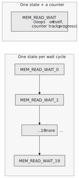
The dedicated wait_count counter, from the Section 3.5 patterns, scales to any wait count by changing one localparam, with no additional states whether the number is 2 or 200. This is the “counter over state explosion” reasoning from Section 3.5, paying off on a case where the state count really would explode.
A simple address decoder
Real systems often have several memory-mapped devices sharing an address bus. This controller needs to know whether an address falls within its memory’s range before asserting anything:
logic addr_in_range;
assign addr_in_range = (addr >= BASE_ADDR) && (addr < BASE_ADDR + MEM_DEPTH);

assign read_req_gated  = read_req  && addr_in_range;
assign write_req_gated = write_req && addr_in_range;
This is the simplest possible decode, one range check, appropriate for a controller managing one contiguous region. A system with several peripherals on a bus needs a decoder distinguishing several disjoint ranges, but the technique, compare the address against this device’s range and gate all requests on the result, is the one that scales.
Practice Exercise
Trace wait_count and the state sequence for a read with READ_WAIT_CYCLES = 2, confirming ready asserts on the correct cycle relative to when read_req was asserted.
Solution
Cycle 0: state = MEM_IDLE, read_req asserted, next_state = MEM_READ_WAIT. Cycle 1: state = MEM_READ_WAIT, wait_count = 0, enables asserted; wait_count != 1, so the state holds and wait_count increments to 1 at the next edge. Cycle 2: still MEM_READ_WAIT, wait_count = 1, which equals READ_WAIT_CYCLES - 1, so next_state = MEM_READ_DONE. Cycle 3: state = MEM_READ_DONE, ready = 1. Exactly 2 cycles (1 and 2) were spent in MEM_READ_WAIT, matching READ_WAIT_CYCLES = 2, with ready asserting only after they elapsed.
This FSM is unusual in an instructive way: most of its states enforce a calculated wait rather than performing a distinct operation, and a dedicated counter rather than a chain of near-identical states is what makes that scale to any datasheet requirement. A range-based decoder gates every request on whether it belongs to this controller. In the next article, the last of this project, we assemble the controller against the timing-accurate model from Part 1, with a testbench that proves the controller respects the timing and would be caught violating it.