Project 2, Part 3: The Transmitter and Receiver FSMs
The previous article produced the ticks. This one uses them.
The transmitter is the easier half, and it is worth being clear why: it knows the whole frame’s timing in advance, since it is the side generating that timing. The receiver has the harder job, reconstructing the timing from an asynchronous edge as Part 1 specified, and its FSM reflects that.
The transmitter: a PISO shift register in a UART frame
Recall the parallel-in, serial-out shift register from Section 3.4: load a byte in one cycle, shift it out one bit per tick. A UART transmitter is that, with the start and stop bits added around the byte:
typedef enum logic [1:0] {TX_IDLE, TX_START, TX_DATA, TX_STOP} tx_state_t;
tx_state_t tx_state, tx_next_state;

logic [7:0] tx_shift_reg;
logic [2:0] bit_count;
logic       tx_line;

// Block 1: state register (Section 5.6 style), advancing only on a bit-period tick
always_ff @(posedge clk or negedge rst_n) begin
    if (!rst_n) tx_state <= TX_IDLE;
    else if (baud_tick) tx_state <= tx_next_state;
end

// Block 2: next-state logic
always_comb begin
    tx_next_state = tx_state;
    unique case (tx_state)
        TX_IDLE:  if (tx_start) tx_next_state = TX_START;
        TX_START: tx_next_state = TX_DATA;
        TX_DATA:  if (bit_count == 3'd7) tx_next_state = TX_STOP;
        TX_STOP:  tx_next_state = TX_IDLE;
        default:  tx_next_state = TX_IDLE;
    endcase
end

// Datapath: the line and the shift register, also stepped on the tick
always_ff @(posedge clk or negedge rst_n) begin
    if (!rst_n) begin
        tx_line <= 1'b1;   // idle high, per the protocol
        bit_count <= 3'b0;
    end else if (baud_tick) begin
        unique case (tx_state)
            TX_IDLE:  begin tx_line <= 1'b1; if (tx_start) tx_shift_reg <= tx_data_in; end
            TX_START: begin tx_line <= 1'b0; bit_count <= 0; end
            TX_DATA:  begin
                tx_line <= tx_shift_reg[0];             // LSB first, per Part 1
                tx_shift_reg <= {1'b0, tx_shift_reg[7:1]};
                bit_count <= bit_count + 1'b1;
            end
            TX_STOP:  tx_line <= 1'b1;
        endcase
    end
end
Every transition is gated by baud_tick, so exactly one bit period elapses between state changes, generating the timing the receiver at the other end will have to reconstruct. The byte is captured in TX_IDLE on the same tick the start request is seen, so the data input only has to be stable at that moment.
The receiver: finding a start bit it was never told about
The receiver’s FSM is structurally similar but has an extra job: detecting the start of a frame at all, from a line that is idle-high until some transmitter decides to send.
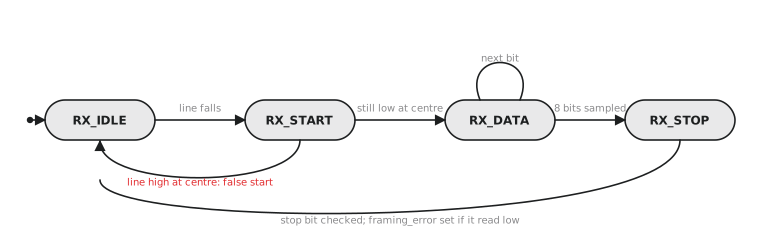
typedef enum logic [1:0] {RX_IDLE, RX_START, RX_DATA, RX_STOP} rx_state_t;
rx_state_t rx_state, rx_next_state;

logic [3:0] tick_count;   // counts 16x ticks within one bit period
logic [2:0] bit_count;
logic [7:0] rx_shift_reg;
logic       framing_error;

always_ff @(posedge clk or negedge rst_n) begin
    if (!rst_n) rx_state <= RX_IDLE;
    else        rx_state <= rx_next_state;   // checked every clk edge
end

always_comb begin
    rx_next_state = rx_state;
    unique case (rx_state)
        RX_IDLE:  if (!rx_line) rx_next_state = RX_START;   // falling edge seen
        RX_START: if (tick_16x && tick_count == 4'd7)        // Part 1's centre-of-start-bit check
                       rx_next_state = rx_line ? RX_IDLE : RX_DATA;   // reject a false start
        RX_DATA:  if (tick_16x && tick_count == 4'd15 && bit_count == 3'd7)
                       rx_next_state = RX_STOP;
        RX_STOP:  if (tick_16x && tick_count == 4'd15)
                       rx_next_state = RX_IDLE;
        default:  rx_next_state = RX_IDLE;
    endcase
end

always_ff @(posedge clk or negedge rst_n) begin
    if (!rst_n) begin
        tick_count <= 0; bit_count <= 0; framing_error <= 1'b0;
    end else if (tick_16x) begin
        unique case (rx_state)
            RX_IDLE:  begin tick_count <= 0; bit_count <= 0; end
            RX_START: tick_count <= (tick_count == 4'd7) ? 4'd0 : tick_count + 1'b1;
            RX_DATA: begin
                if (tick_count == 4'd15) begin
                    rx_shift_reg <= {rx_line, rx_shift_reg[7:1]};   // sample at bit centre, shift in
                    bit_count <= bit_count + 1'b1;
                    tick_count <= 0;
                end else begin
                    tick_count <= tick_count + 1'b1;
                end
            end
            RX_STOP: begin
                if (tick_count == 4'd15)
                    framing_error <= !rx_line;   // stop bit MUST read high: Part 1's failure mode
                tick_count <= tick_count + 1'b1;
            end
        endcase
    end
end
Look at tick_count == 4'd7 in RX_START. That is the centre-of-start-bit confirmation from Part 1, expressed as a count of the 16x tick: 8 sub-ticks into the 16 that make one bit period. The counter then restarts from 0, so in RX_DATA the condition tick_count == 4'd15 fires 16 sub-ticks later, one full bit period after the start bit’s centre, which is the centre of the first data bit, and then every 16 sub-ticks after that.
Practice Exercise
Trace the receiver’s tick_count and bit_count across one byte, confirming exactly 8 samples occur in RX_DATA before the transition to RX_STOP.
Solution
Entering RX_DATA from a confirmed start bit, tick_count counts 0, 1, … 15. At 15 the first data bit is sampled (bit_count becomes 1) and tick_count resets to 0 for the next bit period. Each full 16-tick cycle produces one sample and increments bit_count. On the 8th such cycle, the next-state logic sees bit_count == 7 together with tick_count == 15 (the 8th sample happening on this same tick) and moves to RX_STOP. Exactly 8 centre-sampled bits occur between entering RX_DATA and leaving it, matching the 8-data-bit specification.
The transmitter reuses the Section 3.4 PISO pattern with start and stop bits around the byte and every transition gated by the bit-period tick. The receiver does the harder work: detecting a start bit from an idle line, confirming it is not a glitch by checking its centre against the 16x tick, sampling each data bit at its centre, and checking the stop bit. In the next article, the last for this project, we assemble both into a complete UART and verify the whole loop, transmit a byte, receive it back, check it matches.