Project 2, Part 1: The UART Protocol
Project 1 was a processor. Project 2 is a serial protocol, and we start, as always, with the specification.
UART has come up constantly since Module 3, as the motivating example for shift registers, as an application of counters, as the thing a baud rate tick feeds. This article finally pins down what UART is, precisely enough to implement.
The frame format
A UART frame is a fixed sequence of bits sent serially, one at a time, with no clock line shared between transmitter and receiver. That is the single most important fact about the protocol and the reason its timing has to be precise.
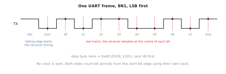
| Field | Width | Value |
|---|---|---|
| Start bit | 1 | Always 0. The transition from idle-high to 0 tells the receiver a frame is beginning |
| Data bits | 5 to 9 (this project: 8) | The byte, sent LSB first |
| Parity bit | 0 or 1 (this project: none) | Optional error-detection bit |
| Stop bit(s) | 1 to 2 (this project: 1) | Always 1, returning the line to idle |
This project uses 8 data bits, no parity, 1 stop bit, “8N1”, the most common configuration and simple enough to implement completely while exercising every structural piece a more elaborate configuration would need.
Why timing is the whole problem
There is no shared clock. The receiver has no direct way to know when the transmitter intends each bit to be sampled. It has to infer the bit boundaries from the falling edge of the start bit and its own independent knowledge of the agreed baud rate (bits per second).
$$T_{bit} = \frac{1}{\text{baud rate}}$$
At 9600 baud each bit lasts about 104.17 microseconds. Both sides generate this timing from their own local clocks, which is what the counter-based dividers from Section 3.5 do, applied here to a protocol-mandated period.
The receiver’s sampling strategy
Given only the start bit’s falling edge as a reference, the receiver samples every following bit as close to its centre as possible. That maximises tolerance for the small clock mismatch between the two sides, since two independent clocks are never identical. Figure 1 shows the sample points. Sampling at the centre rather than at an edge means that timing drift accumulated over several bits still lands the sample well inside the correct bit, rather than at a boundary where drift could put it on the wrong bit.
Failure modes a correct implementation handles
Framing error. If the stop bit does not read high when sampled, something went wrong: a timing mismatch or a corrupted frame. A correct receiver detects and reports this rather than accepting a malformed byte as valid.
False start bit. A glitch on the line could look like a start bit’s falling edge for a few nanoseconds. The centre-of-start-bit confirmation exists to reject this: if the line has returned high by the time the receiver checks the presumed start bit’s centre, it was not a real start and the receiver returns to idle rather than sampling eight data bits from a bogus frame.
Baud rate mismatch. If the two sides are configured for different rates, a common misconfiguration, every sample after the first one or two drifts further from the bit centre until it lands on the wrong bit. The testbench in the last article of this project checks correct behaviour at the configured rate and the exercise there looks at what a mismatch does.
The lack of a shared clock is why UART does not scale to high data rates the way SPI (Project 3) or a synchronous bus does. Every increase in baud rate shrinks the tolerance window for clock mismatch, which is why UART lives at low to moderate speeds, debug consoles and simple sensor links, and is absent from high-bandwidth interfaces.
Practice Exercise
Given a 50 MHz system clock and a target of 115200 baud, calculate how many clock cycles make one bit period, and how many make a half-bit period (the delay to reach the centre of the start bit).
Solution
One bit period: $\frac{50{,}000{,}000}{115200} \approx 434.03$ cycles, rounded to 434 for a counter-based implementation (the Section 3.5 modulo-N pattern with $N = 434$).
Half a bit period: $434 / 2 = 217$ cycles. That is the delay the receiver’s FSM waits after the start bit’s falling edge before its confirmation sample, landing as close to the start bit’s centre as this clock resolution allows.
A UART frame is a simple fixed sequence, start bit, data LSB first, optional parity, stop bit, but the absence of a shared clock is what makes it non-trivial to implement: both sides derive matching timing from their own clocks, and the receiver samples at bit centres to tolerate the mismatch. In the next article we build the baud rate generator, the counter that turns the system clock into the bit-timing ticks the whole protocol depends on.