Project 1, Part 2: The Datapath
The previous article fixed the ISA. This one builds the hardware that moves the data, and the good news is that there is no new hardware concept in it. The datapath, the register file, the ALU and the muxes between them, is assembled from things you already have working code for: the ALU from Module 2 with the parameterization from Module 7, and a register file structurally the same as the one in Section 3.6. This article is about wiring, not invention.
The building blocks
The ALU. Reuse the parameterized ALU from the Section 7.1 worked example. It already supports ADD, SUB, AND and OR, the four R-type operations this ISA needs, selected by an opcode that lines up with this project’s encoding.
The register file. A 4-entry, 8-bit register file, the multi-port register bank from Section 3.6 sized to this ISA’s 2-bit select:
module reg_file (
    input  logic       clk,
    input  logic [1:0] rd_addr_a, rd_addr_b, wr_addr,
    input  logic [7:0] wr_data,
    input  logic       wr_en,
    output logic [7:0] rd_data_a, rd_data_b
);
    logic [7:0] regs [0:3];

    assign rd_data_a = regs[rd_addr_a];   // combinational read, as in Section 3.6
    assign rd_data_b = regs[rd_addr_b];

    always_ff @(posedge clk) begin
        if (wr_en) regs[wr_addr] <= wr_data;
    end
endmodule
The memory. Reuse the parameterized single-port memory from Section 7.1, ram_sp, with DATA_WIDTH = 8, once for instructions and once for data.
Assembling the datapath
The datapath’s job: given the decoded fields (opcode, Rd, Rs, Imm/Addr), route the right operands into the ALU and route the result, from the ALU, the memory or the immediate, to the right destination.
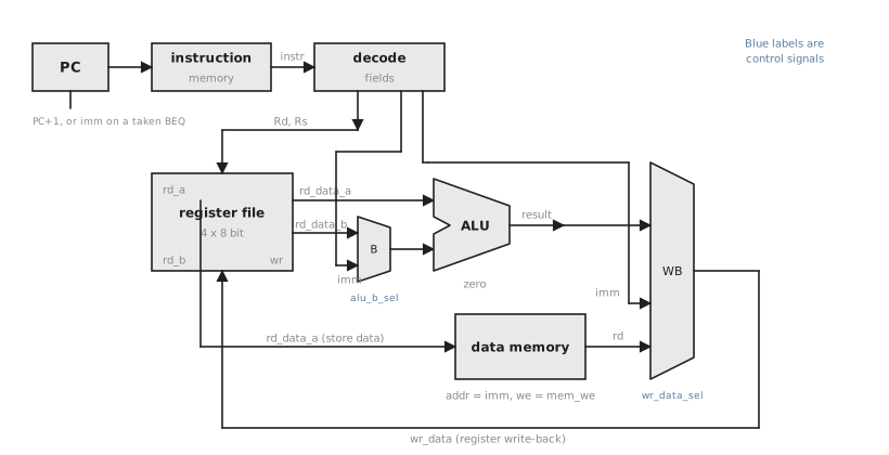
Two muxes do the architectural work, and each exists for a nameable reason.
The ALU B-input mux exists because the R-type instructions need Rs’s register value as the second operand, while nothing else in the ISA does. Rather than build a second arithmetic path for those four instructions, routing either the register value or the immediate through the same ALU input keeps one shared ALU doing all the arithmetic, which is the resource-sharing idea from Section 8.2 applied at the architecture level instead of left to the synthesis tool.
The write-back mux exists because three different sources can end up in a register: the ALU result (R-type), a value read from memory (LD), or the immediate itself (LDI). The control unit in the next article decides which one feeds wr_data on a given cycle, based on the opcode.
What the datapath needs from control
Everything in Figure 1 is either a data wire or a mux, and every mux needs a select from somewhere. This article deliberately leaves every select, along with wr_en, the memory write enable and the PC update, undriven. That is the explicit handoff to the next article. Listed out, this is the control unit’s entire interface:
- ALU B mux select (register
Rsversus immediate) - Write-back mux select (ALU result, memory data, or immediate)
- Register file
wr_en - Data memory
we, forST - PC update: increment, or branch target, and the branch condition itself
This separation, datapath moves data and control decides when and which way, is the FSM-plus-datapath pattern from the vending machine example in Section 5.6, at the scale of a processor instead of a small state machine. The pattern does not change with scale; only the number of signals the control unit has to sequence does.
Practice Exercise
Trace the datapath, mux by mux, for LDI R2, 6. Identify which path through Figure 1 is active and which is unused.
Solution
For LDI R2, 6 the ALU is unused; there is no register arithmetic. The write-back mux selects the immediate input, routing the decoded Imm field (6) to wr_data. wr_addr is R2 and wr_en is asserted for one cycle. The data memory is untouched. This is a different, shorter path than an ADD takes (both register reads, the ALU, then the write-back mux selecting the ALU result), which confirms the mux structure supports several different data flows through the same shared hardware, as intended.
The datapath is assembled from reused, verified components, the parameterized ALU and memory from Section 7.1 and a register file like the one in Section 3.6, connected by two muxes whose existence traces directly to the ISA. Every select and enable is left undriven here as the contract for the next article, which builds the control unit that drives them, cycle by cycle, for every instruction.