Project 2, Part 2: The Baud Rate Generator
The previous article specified the timing. This one builds the counter that produces it: the Section 3.5 modulo-N counter, sized to the cycle count the previous exercise calculated, and parameterized so the same module handles any system clock and any baud rate.
The transmitter’s tick: one pulse per bit period
module baud_tick_gen #(
    parameter CLK_FREQ  = 50_000_000,
    parameter BAUD_RATE = 115200
) (
    input  logic clk, rst_n,
    output logic tick   // one-cycle pulse, once per bit period
);
    localparam int DIVISOR = CLK_FREQ / BAUD_RATE;
    logic [$clog2(DIVISOR)-1:0] count;

    always_ff @(posedge clk or negedge rst_n) begin
        if (!rst_n) begin
            count <= 0;
            tick  <= 1'b0;
        end else if (count == DIVISOR - 1) begin
            count <= 0;
            tick  <= 1'b1;
        end else begin
            count <= count + 1'b1;
            tick  <= 1'b0;
        end
    end
endmodule
This is the modulo-N counter from Section 3.5, wrapping at DIVISOR - 1, with the $clog2 width discipline from Section 7.1, so the same module produces 434-cycle ticks for this project’s 50 MHz, 115200 baud configuration or any other combination by changing the two parameters.
Why the receiver wants a faster tick
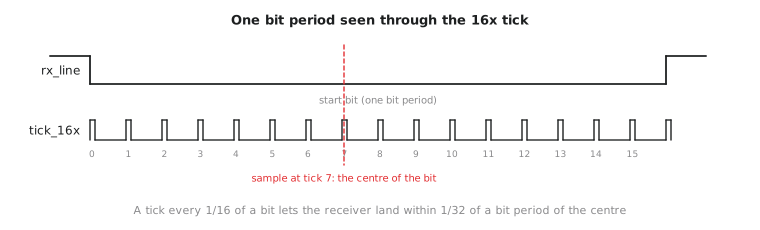
The transmitter needs one tick per bit; it produces the timing, so there is nothing to synchronize against. The receiver’s problem is different: it has to find the centre of each bit starting from an asynchronously arriving start edge it had no warning of. A single tick per bit gives it one shot per bit at landing correctly, with no finer resolution to compensate if that tick fires a little early or late.
The standard fix, used in essentially every real UART: a tick 16 times faster than the bit rate. The receiver counts 16 of them per bit period and samples the line at the eighth, the midpoint. Figure 1 shows one bit period seen through this tick.
module baud_tick_gen_16x #(
    parameter CLK_FREQ  = 50_000_000,
    parameter BAUD_RATE = 115200
) (
    input  logic clk, rst_n,
    output logic tick_16x
);
    localparam int DIVISOR_16X = CLK_FREQ / (BAUD_RATE * 16);
    logic [$clog2(DIVISOR_16X)-1:0] count;

    always_ff @(posedge clk or negedge rst_n) begin
        if (!rst_n) begin
            count <= 0; tick_16x <= 1'b0;
        end else if (count == DIVISOR_16X - 1) begin
            count <= 0; tick_16x <= 1'b1;
        end else begin
            count <= count + 1'b1; tick_16x <= 1'b0;
        end
    end
endmodule
The factor of 16 is a trade. A higher oversampling ratio gives finer resolution for finding the bit centre and more tolerance for clock mismatch, at the cost of a faster internal tick and more logic transitions, a small power cost in the Section 7.6 sense. 16 is where real UART peripherals almost universally land.
Baud rate error from integer division
An honest limitation: CLK_FREQ / BAUD_RATE is an integer division, and it essentially never divides evenly for a real system clock and a standard baud rate. That introduces a small, unavoidable timing error:
$$\text{Actual Baud Rate} = \frac{CLK_FREQ}{DIVISOR} \qquad \text{Error} = \left| \frac{\text{Actual} - \text{Target}}{\text{Target}} \right| \times 100%$$
For 50 MHz at 115200 baud: $DIVISOR = \lfloor 50{,}000{,}000 / 115200 \rfloor = 434$, giving an actual rate of about 115,207 baud, an error around 0.006 percent, negligible. It is not always this forgiving. Some clock and baud combinations give errors above 2 percent, which is near the practical limit real UART hardware absorbs before framing errors appear from drift alone. Checking the error for your configuration is a standard step in any real UART design, and microcontroller datasheets publish tables of achievable rates and their error for each system clock precisely because of this.
Practice Exercise
Calculate the baud rate error for a 16 MHz system clock targeting 9600 baud, and say whether the configuration is acceptable.
Solution
$DIVISOR = \lfloor 16{,}000{,}000 / 9600 \rfloor = 1666$ (the exact quotient is 1666.67).
Actual rate: $16{,}000{,}000 / 1666 \approx 9603.8$ baud.
Error: $|9603.8 - 9600| / 9600 \times 100% \approx 0.04%$, well within tolerance. This is a very common real configuration precisely because the error is this small.
The baud rate generator is the Section 3.5 modulo-N counter, parameterized to the divisor a given clock and baud rate require, in two versions: one tick per bit for the transmitter and a 16x tick giving the receiver the resolution the centre-sampling strategy needs. Integer division introduces a small, calculable error worth checking for any real configuration. In the next article we build the transmitter and receiver FSMs that use these ticks to put UART frames onto the line and take them off.