Project 3, Part 1: SPI and Its Four Modes
Project 2 spent an article on the consequences of having no shared clock: drift, centre sampling, framing errors. SPI makes the opposite bet. Share a clock line and nearly all of that fragility disappears. What is left is a much simpler timing story with one remaining wrinkle: the shared clock has two independent configuration choices, and both sides have to agree on both.
Why sharing a clock solves UART’s problem
With a clock line (SCLK) running from master to slave there is nothing to reconstruct. The slave does not guess where a bit boundary is, because the master tells it, every edge. This is the synchronous-design principle from Module 3 applied between chips rather than within one: shared clock, shared timing reference, no drift because nothing is inferred independently on either side.
The two configuration bits: CPOL and CPHA
SPI does not mandate one fixed relationship between clock and data. It defines two independent bits, and every peripheral’s datasheet says which combination it expects.
CPOL, clock polarity, is the clock’s idle state between transactions: CPOL = 0 idles low, CPOL = 1 idles high.
CPHA, clock phase, is which clock edge data is sampled on: CPHA = 0 samples on the first (leading) edge of each pulse, CPHA = 1 on the second (trailing) edge.
Two bits, four combinations, which are SPI’s four named modes:
| Mode | CPOL | CPHA | Clock idles | Data sampled on |
|---|---|---|---|---|
| 0 | 0 | 0 | Low | Rising (leading) edge |
| 1 | 0 | 1 | Low | Falling (trailing) edge |
| 2 | 1 | 0 | High | Falling (leading) edge |
| 3 | 1 | 1 | High | Rising (trailing) edge |
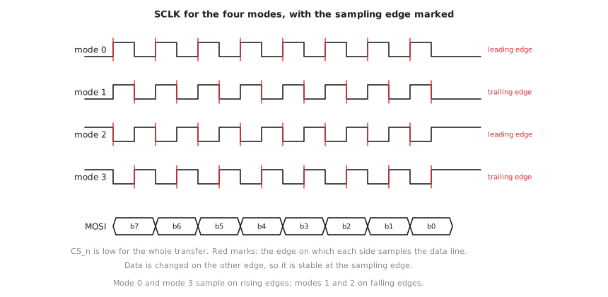
Figure 1 shows the four clocks side by side. Note that “leading edge” is a rising edge when the clock idles low and a falling edge when it idles high, which is why modes 0 and 3 both sample on rising edges even though they differ in both bits. Data is changed on the opposite edge from the sampling edge, so it is stable when sampled.
Why getting this wrong is a common bug
Connect a master configured for mode 0 to a slave expecting mode 3 and the master shifts data out and samples data in on the wrong edges relative to what the slave does. Every bit transferred is potentially garbage, not because either side’s SPI logic has a bug in isolation but because they disagree about which edge means what. This is a common real-world integration bug, precisely because it is easy to build and verify a master or slave on its own (this project’s approach) and only discover a mode mismatch on connecting to a specific peripheral whose datasheet specifies a mode you did not build for.
This project’s scope: a master configurable across all four modes
Given how common mode mismatches are, this project builds a master configurable across all four modes through CPOL and CPHA inputs, rather than hard-wiring one. That is the Section 7.1 parameterization discipline, expressed as runtime inputs rather than compile-time parameters, because a real master often talks to several peripherals that may need different modes without being resynthesized for each.
Practice Exercise
A datasheet says: “SCLK idles high; data is valid and should be sampled on SCLK’s falling edge, which is the first (leading) edge of each clock pulse from the idle-high state.” Which mode is this?
Solution
“SCLK idles high” is CPOL = 1. “Sampled on the leading edge” is CPHA = 0. From the table, CPOL=1, CPHA=0 is mode 2. The care needed here is that from an idle-high clock, the leading edge of the first pulse is a falling edge, since the clock is moving away from its high idle, which matches the datasheet’s description. This is exactly the edge-by-edge reasoning a real datasheet requires before writing any RTL, and why this article comes before any implementation.
SPI trades UART’s fragility for a shared clock, eliminating drift and centre sampling, but the shared clock carries two configuration choices, CPOL and CPHA, combining into four modes a master and slave must agree on exactly. This project builds a master configurable across all four. In the next article we build the shift register datapath and the chip-select framing that implements whichever mode is configured.