Fixing a Post-CTS Hold Violation
The previous article left the UART with a six-picosecond hold violation between u_rx_baud/count_reg[0] and count_reg[1]. Small in absolute terms, but a real violation that Module 7’s signoff checks would flag and refuse to pass. Six picoseconds is also an easy fix. This article closes it and shows the report confirming it worked.
Two standard fixes, and why this one
You have already met both options separately. Insert a small delay buffer on the failing data path, which adds to (t_{comb}) and, per the hold equation, directly increases hold slack. Or adjust useful skew so the launching register’s latency is relatively later, which also increases hold slack, from the latency side of the same equation.
For this violation, buffer insertion on the data path is the more surgical choice. It touches only this one path’s delay and leaves the clock tree, which Section 5.3 already tuned to meet its skew target across the whole design, undisturbed. Adjusting skew would mean re-touching the tree at count_reg[1]’s leaf, with possible consequences for every other path sharing that leaf or buffer. Disturbing one data path is lower risk than disturbing shared clock infrastructure.
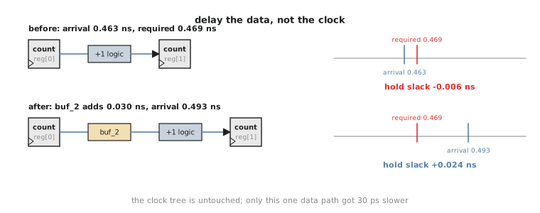
Applying the fix
OpenROAD’s resizer exposes exactly this as a timing repair command, run interactively after CTS and before routing:
% repair_timing -hold
[INFO RSZ-0047] Found 1 endpoint with hold violations.
[INFO RSZ-0048] Inserting hold buffer on path:
                 u_rx_baud/count_reg[0] -> u_rx_baud/count_reg[1]
[INFO RSZ-0049] Buffer inserted: sky130_fd_sc_hd__buf_2 (u_rx_baud/hold_fix_buf_0)
[INFO RSZ-0050] Repaired 1 of 1 hold violations.
repair_timing -hold scans the endpoints already known to violate hold and inserts the smallest buffer from the available variants that closes each one without overcorrecting. A buf_2, a small, low-drive buffer, is exactly the minimal insertion a six-picosecond gap calls for. In practice OpenROAD often picks a dedicated delay cell for hold fixes; the log above is representative of the shape rather than the exact cell.
Confirming the fix
Rerun the same hold check on this path:
Startpoint: u_rx_baud/count_reg[0] (rising edge-triggered flip-flop clocked by clk)
Endpoint:   u_rx_baud/count_reg[1] (rising edge-triggered flip-flop clocked by clk)
Path Group: clk
Path Type:  min

  Delay    Time   Description
--------------------------------------------------------------
   0.000   0.000   clock clk (rise edge)
   0.298   0.298   clock network delay (propagated)
   0.000   0.298   u_rx_baud/count_reg[0]/CLK (sky130_fd_sc_hd__dfxtp_2)
   0.095   0.393   u_rx_baud/count_reg[0]/Q
   0.030   0.423   u_rx_baud/hold_fix_buf_0/Y (sky130_fd_sc_hd__buf_2)
   0.070   0.493   u_rx_baud/count_reg[1]/D (data arrival time)
--------------------------------------------------------------
   0.000   0.000   clock clk (rise edge)
   0.409   0.409   clock network delay (propagated)
   0.000   0.409   u_rx_baud/count_reg[1]/CLK
   0.060   0.469   library hold time
                    data required time                 0.469
--------------------------------------------------------------
   data required time                                  0.469
   data arrival time                                    0.493
--------------------------------------------------------------
   slack (MET)                                          0.024
The buffer’s 0.030 ns pushed arrival from 0.463 ns to 0.493 ns, comfortably past the 0.469 ns the check requires, landing at +0.024 ns of margin. The violation is closed.
The setup check you must not skip
Adding delay to a data path fixes hold, but the same term cuts both ways. More (t_{comb}) helps hold and costs setup, since setup subtracts (t_{comb}) from the period. Any real hold fix has to be re-checked against setup on the same path:
$$\text{Setup slack (before)} = 20.000 - (0.070 + t_{setup} + \text{skew term}) \qquad \text{Setup slack (after)} = 20.000 - (0.100 + t_{setup} + \text{skew term})$$
The 0.030 ns costs setup slack directly, but against a 20 ns period with roughly nineteen and a half nanoseconds of setup margin on paths through this counter, thirty picoseconds is trivially absorbed. That will not always be true. A design with a tight setup margin on the same path would have to weigh a hold fix’s setup cost far more carefully, and might fall back to the useful-skew alternative instead.
This tension, hold fixes cost setup and setup fixes such as Module 7’s buffer insertion and gate resizing can reintroduce hold problems elsewhere, is why real signoff closure in Module 7 runs as an iterative loop across every corner and every violation class at once, not as isolated one-off fixes. This article fixed one path in isolation because at 50 MHz with this much setup headroom it is safe to. A tighter design would not have that luxury.
Practice Exercise
Suppose the UART’s setup margin on the u_rx_baud counter path had been only 0.040 ns instead of nineteen-plus nanoseconds. Would the 0.030 ns hold-fix buffer still be a safe choice? What would you check before committing to it?
Solution
Far riskier, though not automatically wrong. With 0.040 ns of setup margin, adding 0.030 ns of delay leaves 0.010 ns, technically passing but uncomfortably close to a new violation from any extra source of variation: on-chip variation, corner-to-corner shift in Module 7’s multi-corner analysis, or a slightly larger buffer than strictly needed. Before committing you would rerun setup on this exact path post-fix, as this article did for hold, and seriously consider the useful-skew alternative instead, since it addresses hold from the latency side and leaves the path’s setup margin untouched.
The UART’s clock tree is built, verified and free of the hold violation it exposed. Section 5.5 closes the module by bringing RTL-level clock gating back into the picture: how it is realised physically, and what it means for CTS to treat a gated sub-tree correctly.