Why the Tree Needs Buffers
Every topology so far, H-tree, balanced tree, mesh, has been drawn as if the wires were the whole story: pick a shape, route the wire, done. Real clock wires cannot be left that way, and the reason is not really delay at all. It is the shape of the signal degrading as it travels.
Delay is not the only thing that gets worse
A clock edge is not a step function. It is a real voltage transition with a finite rise and fall time, collectively called slew. As the edge propagates down a long RC wire, the network does not just delay it, it slows it down. The transition from low to high takes measurably longer to complete the further the edge has travelled. A crisp edge at the driver can arrive at the far end of a long wire looking sluggish and rounded.
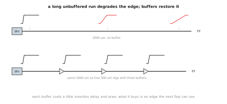
That matters for more than aesthetics. A slow-slewing clock edge means every flop’s internal latch takes longer to resolve what it is capturing, which adds uncertainty and delay on top of the wire’s propagation delay. Over a long enough run, degraded slew becomes a real functional and timing risk.
A buffer, or an inverter pair used for the same purpose in many real clock trees, inserted partway along a branch does one job here. It takes whatever degraded edge arrives at its input and drives out a fresh, full-strength, full-slew edge. It restores signal quality rather than just adding an active gate for its own sake. This is the “signal regeneration at every stage” idea from the very first article of the Verilog course, applied specifically to the clock network. It is also why H-trees, balanced trees and meshes are never built out of raw wire in a real design of any size. Every one of them is, in practice, a buffered topology. The shape controls skew and latency structure; the buffers along each branch control signal integrity. Two different problems that happen to live in the same network.
Buffer placement is a CTS decision
Where each buffer goes, and how many stages a branch needs, is a decision TritonCTS makes as part of building the tree. Buffers too far apart and slew degrades past what downstream cells tolerate. Too close together and you have spent extra area, extra power and extra insertion delay, which itself becomes part of the latency and skew budget from Section 5.1, for no benefit. Sizing matters too. A bigger buffer drives a longer run before the next one is needed, at the cost of more area and power per instance.
Computing the buffer count
Assume, illustratively, that a library and process tolerate a maximum unbuffered run of 600 um before slew degrades past the acceptable limit. A branch needs to reach a flop 2,000 um from the nearest upstream buffer. Splitting it into equal legs no longer than 600 um, how many buffers does it need?
Number of equal legs: (\lceil 2000 / 600 \rceil = \lceil 3.33 \rceil = 4), each 500 um, comfortably under the limit. Four legs means three hand-off points, so the branch needs 3 buffers. In general, for a branch of length (L) and a maximum unbuffered run of (L_{max}), the buffer count is (\lceil L / L_{max} \rceil - 1).
In a real OpenLane flow you do not decide these counts and positions by hand. TritonCTS does, using the library’s actual buffer variants and the SKY130 wire RC. The 600 um figure is a stand-in to build intuition, not a number you would put in a config. And do not think of clock buffers purely as delay elements, the way you might think of a buffer dropped on a data path during Module 7’s ECO work. On the clock network they are as much about restoring the edge as about adding controlled delay.
Practice Exercise
The same library tolerates 600 um unbuffered. A different branch runs 1,500 um. How many buffers, and how long is each leg?
Solution
(\lceil 1500 / 600 \rceil = \lceil 2.5 \rceil = 3) legs of 500 um each, so 2 buffers. Two legs of 750 um would have been fewer buffers but each leg would exceed the 600 um limit, which is exactly the constraint that forces the third leg.
You now understand the why behind every structural piece of a clock tree: topology, balance and buffering. Section 5.3 stops being conceptual. It looks at how TritonCTS actually builds one of these trees for a real design, and the config knobs that steer it.