Three Complete State Machines
These are the three machines of section 3.3, designed there on paper. Nothing about them has changed; only the notation has. This article builds all three as synthesisable RTL with testbenches, which is the point of the whole module: the theory of Module 3 and the code of Module 5 are one thing seen from two distances.
A traffic light
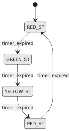
Four states, RED, GREEN, YELLOW and PED, each held for a number of cycles set by timer_in. Three lamp outputs, each a function of the state alone: a Moore machine (Figure 1).
`timescale 1ns / 1ps
`default_nettype none

module traffic_light (
    input  wire       clk,
    input  wire       rst_n,
    input  wire [2:0] timer_in,    // cycles in each state
    output reg        red, green, yellow
);
    localparam [1:0] RED_ST    = 2'b00,
                     GREEN_ST  = 2'b01,
                     YELLOW_ST = 2'b10,
                     PED_ST    = 2'b11;

    reg  [1:0] state, next_state;
    reg  [2:0] timer_count;
    wire       timer_expired = (timer_count == 3'd0);

    // state register
    always @(posedge clk or negedge rst_n) begin
        if (!rst_n) state <= RED_ST;
        else        state <= next_state;
    end

    // the timer: reloads on every transition, counts down otherwise
    always @(posedge clk or negedge rst_n) begin
        if (!rst_n)
            timer_count <= timer_in;
        else if (state != next_state)
            timer_count <= timer_in;
        else if (timer_count != 3'd0)
            timer_count <= timer_count - 1'b1;
    end

    // next state
    always @(*) begin
        next_state = state;
        case (state)
            RED_ST:    if (timer_expired) next_state = GREEN_ST;
            GREEN_ST:  if (timer_expired) next_state = YELLOW_ST;
            YELLOW_ST: if (timer_expired) next_state = PED_ST;
            PED_ST:    if (timer_expired) next_state = RED_ST;
            default:                      next_state = RED_ST;
        endcase
    end

    // Moore outputs
    always @(*) begin
        red = 1'b0; green = 1'b0; yellow = 1'b0;
        case (state)
            RED_ST:    red    = 1'b1;
            GREEN_ST:  green  = 1'b1;
            YELLOW_ST: yellow = 1'b1;
            // PED_ST: all off; a real design drives a walk lamp here
        endcase
    end
endmodule
The timer is a small datapath beside the state machine, the pattern the vending machine uses more seriously below.
module tb_traffic_light;
    reg        clk = 0, rst_n;
    reg  [2:0] timer_in;
    wire       red, green, yellow;

    traffic_light dut (.clk(clk), .rst_n(rst_n), .timer_in(timer_in), .red(red), .green(green), .yellow(yellow));
    always #5 clk = ~clk;

    initial begin
        $dumpfile("tb.vcd");
        $dumpvars(0, tb_traffic_light);

        timer_in = 3'd2;
        rst_n = 0; @(negedge clk); rst_n = 1;

        repeat (20) begin
            @(negedge clk);
            $display("t=%0t state=%b red=%b green=%b yellow=%b", $time, dut.state, red, green, yellow);
        end
        $finish;
    end
endmodule
In the waveform each lamp holds for timer_in + 1 cycles and the next takes over on the following edge, with no gap and no overlap, which is the Moore property: outputs are a clean function of the registered state.
A sequence detector
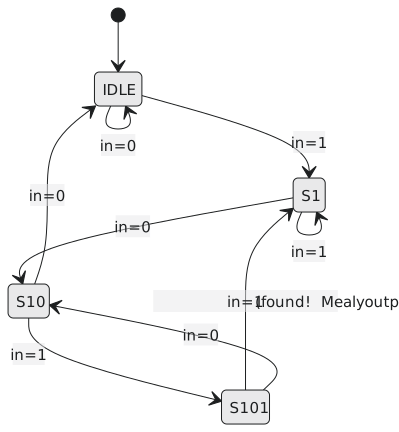
Watch a serial line and pulse found in the cycle the last bit of 1011 arrives, including overlapping occurrences. The subtlety is where to go after a match. Not to the start: the final 1 of a match can be the first 1 of the next, so the machine lands in the state that has already seen one leading 1 (Figure 2).
`timescale 1ns / 1ps
`default_nettype none

module seq_detector_1011 (
    input  wire clk, rst_n, bit_in,
    output reg  found
);
    localparam [2:0] IDLE = 3'd0, S1 = 3'd1, S10 = 3'd2, S101 = 3'd3;
    reg [2:0] state, next_state;

    always @(posedge clk or negedge rst_n) begin
        if (!rst_n) state <= IDLE;
        else        state <= next_state;
    end

    always @(*) begin
        next_state = state;
        found      = 1'b0;
        case (state)
            IDLE: if (bit_in)  next_state = S1;
            S1:   if (!bit_in) next_state = S10;        // another 1: stay in S1
            S10:  if (bit_in)  next_state = S101;
                  else         next_state = IDLE;
            S101: if (bit_in) begin
                      found      = 1'b1;    // Mealy: state and bit_in
                      next_state = S1;      // this 1 may start the next match
                  end else begin
                      next_state = S10;     // 1010: the last 10 is a useful prefix
                  end
            default: next_state = IDLE;
        endcase
    end
endmodule
found is Mealy, so it is valid in the cycle the last bit is on the line and before the edge. The testbench samples it there:
module tb_seq_detector_1011;
    reg     clk = 0, rst_n, bit_in;
    wire    found;
    integer match_count = 0;

    seq_detector_1011 dut (.clk(clk), .rst_n(rst_n), .bit_in(bit_in), .found(found));
    always #5 clk = ~clk;

    // 10110111011 contains 1011 at positions 0, 3 and 7; the second and third overlap their neighbours
    reg [10:0] stream = 11'b10110111011;
    integer    i;

    initial begin
        $dumpfile("tb.vcd");
        $dumpvars(0, tb_seq_detector_1011);

        rst_n = 0; bit_in = 0; @(negedge clk); rst_n = 1;

        for (i = 10; i >= 0; i = i - 1) begin
            bit_in = stream[i];          // set after a falling edge
            #2;                          // let the combinational output settle
            if (found) match_count = match_count + 1;
            @(negedge clk);              // the rising edge in between updates the state
        end

        if (match_count == 3)
            $display("PASS: %0d matches", match_count);
        else
            $display("FAIL: %0d matches (expected 3)", match_count);

        $finish;
    end
endmodule
Three matches from eleven bits is only possible because of the arc from S101 back to S1; a detector that returned to IDLE would find one.
A vending machine
Accept nickels, dimes and quarters on a 2-bit coin_type, 00 for none, dispense at 50 cents, and return change. Should the credit be a state? You could make one state per amount, and it would be a dozen states doing what a register does better. The right shape is a small state machine that decides when to accumulate, dispense and clear, and a small datapath, a register and an adder, that holds the amount. This split between control and datapath is one of the commonest structures in RTL and a good place to end the module.
`timescale 1ns / 1ps
`default_nettype none

// the datapath: accumulated credit in cents
module credit_datapath (
    input  wire       clk, rst_n,
    input  wire [1:0] coin_type,
    input  wire       clear_credit,
    output reg  [6:0] credit
);
    always @(posedge clk or negedge rst_n) begin
        if (!rst_n)            credit <= 7'd0;
        else if (clear_credit) credit <= 7'd0;
        else case (coin_type)
            2'b01:   credit <= credit + 7'd5;
            2'b10:   credit <= credit + 7'd10;
            2'b11:   credit <= credit + 7'd25;
            default: credit <= credit;
        endcase
    end
endmodule

// the controller
module vending_controller #(
    parameter [6:0] PRICE = 7'd50
) (
    input  wire       clk, rst_n,
    input  wire [1:0] coin_type,
    input  wire [6:0] credit,
    output reg        clear_credit,
    output reg        dispense,
    output reg  [6:0] change_out
);
    localparam [1:0] IDLE = 2'b00, ACCUMULATING = 2'b01, DISPENSING = 2'b10;
    reg [1:0] state, next_state;

    always @(posedge clk or negedge rst_n) begin
        if (!rst_n) state <= IDLE;
        else        state <= next_state;
    end

    always @(*) begin
        next_state   = state;
        clear_credit = 1'b0;
        dispense     = 1'b0;
        change_out   = 7'd0;
        case (state)
            IDLE:         if (coin_type != 2'b00) next_state = ACCUMULATING;
            ACCUMULATING: if (credit >= PRICE)    next_state = DISPENSING;
            DISPENSING: begin
                dispense     = 1'b1;
                change_out   = credit - PRICE;
                clear_credit = 1'b1;          // the datapath clears at this edge
                next_state   = IDLE;
            end
            default: next_state = IDLE;
        endcase
    end
endmodule

// the top: controller and datapath wired together
module vending_machine #(
    parameter [6:0] PRICE = 7'd50
) (
    input  wire       clk, rst_n,
    input  wire [1:0] coin_type,
    output wire       dispense,
    output wire [6:0] change_out
);
    wire       clear_credit;
    wire [6:0] credit;

    credit_datapath u_datapath (
        .clk(clk), .rst_n(rst_n), .coin_type(coin_type), .clear_credit(clear_credit), .credit(credit)
    );

    vending_controller #(.PRICE(PRICE)) u_controller (
        .clk(clk), .rst_n(rst_n), .coin_type(coin_type), .credit(credit),
        .clear_credit(clear_credit), .dispense(dispense), .change_out(change_out)
    );
endmodule
The DISPENSING state does three things in its one cycle: raises dispense, presents the change, and tells the datapath to clear, so the next customer starts from zero. Exact change and overpayment go the same way; the change is simply zero in the first case.
module tb_vending_machine;
    reg        clk = 0, rst_n;
    reg  [1:0] coin_type;
    wire       dispense;
    wire [6:0] change_out;

    vending_machine dut (.clk(clk), .rst_n(rst_n), .coin_type(coin_type), .dispense(dispense), .change_out(change_out));
    always #5 clk = ~clk;

    task insert_coin;
        input [1:0] c;
        begin
            coin_type = c;     @(negedge clk);
            coin_type = 2'b00; @(negedge clk);
        end
    endtask

    task expect_dispense;
        input [6:0] exp_change;
        integer guard;
        begin
            guard = 0;
            while (!dispense && guard < 10) begin @(negedge clk); guard = guard + 1; end
            if (dispense && change_out == exp_change)
                $display("PASS: dispensed, change=%0d", change_out);
            else
                $display("FAIL: dispense=%b change_out=%0d (expected change %0d)", dispense, change_out, exp_change);
            @(negedge clk);                   // let it return to IDLE
        end
    endtask

    initial begin
        $dumpfile("tb.vcd");
        $dumpvars(0, tb_vending_machine);

        rst_n = 0; coin_type = 2'b00; @(negedge clk); rst_n = 1;

        insert_coin(2'b11); insert_coin(2'b11);                     // 50: exact
        expect_dispense(7'd0);

        insert_coin(2'b11); insert_coin(2'b11); insert_coin(2'b10); // 60: ten back
        expect_dispense(7'd10);

        $finish;
    end
endmodule
Two purchases, two outcomes, and the controller never did arithmetic: the datapath tracked every cent, and the controller decided when to read it, when to clear it, and what to hand back.
Module 5 in review
Procedural blocks. Every always, assign and instance runs at once. always is hardware and initial is not. = in combinational blocks, <= in clocked ones, never mixed, and the two-phase time step is why.
Sensitivity lists. An edge means a flip-flop, a level means logic. @(*) for every combinational block. A missing signal is storage in the simulation that the silicon does not have; a missing else or default is storage in the silicon you did not ask for. Defaults at the top of every combinational block.
if and case. An if chain is a priority mux chain, right when one condition must beat another. A case on distinct constants is a flat decoder. casez for wildcards and never casex. The pragmas promise things the simulator cannot check; write the default instead.
Loops. A for with constant bounds is unrolled into parallel hardware. repeat, while and forever are for testbenches. generate for repeats structure and names each copy.
Registers. always @(posedge clk) infers flip-flops. Asynchronous reset asserted at once and released through a synchroniser. Enables map to the clock-enable pin, and a clock is never gated with an AND. Six register patterns, and pipelines that trade latency for clock rate with a valid bit alongside the data.
State machines. Three circuits in one, two or three blocks. Encodings by localparam, one-hot for FPGAs and binary for ASICs. A default arm so that an illegal state recovers. Control and datapath kept apart.
Module 5 has been about writing RTL that becomes the hardware you meant. Module 6 turns around and asks how you know: testbenches, stimulus, and the self-checking that proves it.