Non-Blocking Assignments
The last article ended on a race: two clocked blocks sharing a signal, with blocking assignments, and a result that depends on which block the simulator runs first. The non-blocking assignment, <=, is the fix, and it is not a convention; it is a mechanism designed to make sequential logic simulate correctly whatever order the blocks run in.
Two phases
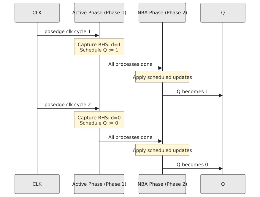
When a clock edge fires, every block sensitive to it becomes active and the simulator runs them one at a time in some order. With <= the time step has two parts.
In the first, each block runs. At q <= d, the right-hand side is evaluated now and the value saved, and the update of q is put on a list for later. The block carries on; q has not changed.
In the second, after every active block has finished, all the saved updates are applied together.
So during the first phase every block reads every signal as it was at the start of the step, and no block sees any other block’s <= until the second phase, when they all land at once. The order in the first phase no longer matters.
The flip-flop
`timescale 1ns / 1ps
`default_nettype none

module dff (
    input  wire clk,
    input  wire d,
    output reg  q
);
    always @(posedge clk) begin
        q <= d;
    end

endmodule
At the edge, d is read, its value saved, the update scheduled; after all blocks have run, q takes it. q gets the value d had at the edge, and if some other block changes d in the same step with a <=, q does not see that. That is what a flip-flop does: it samples at the edge.
The swap
Exchange two registers in one cycle. With blocking assignments:
// wrong
always @(posedge clk) begin
    a = b;
    b = a;     // reads the a that was just overwritten with b
end
After the first line a holds the old b; the second line copies that back into b, and both hold the old b. The software fix is a temporary. With non-blocking assignments no temporary is needed:
always @(posedge clk) begin
    a <= b;    // save old b for a
    b <= a;    // save old a for b; a has not changed yet
end
| phase 1, line 1 | read b, schedule a := old b |
| phase 1, line 2 | read a, still the old a, schedule b := old a |
| phase 2 | apply both |
They swap. It works whether the two lines are in one block or in two, because the second phase collects updates from every block. It is the two cross-connected flip-flops of section 4.1, and the simulator now behaves like them.
A pipeline
`timescale 1ns / 1ps
`default_nettype none

module pipeline_3stage #(
    parameter WIDTH = 8
) (
    input  wire             clk,
    input  wire             rst,
    input  wire [WIDTH-1:0] data_in,
    output wire [WIDTH-1:0] stage3_out
);
    reg [WIDTH-1:0] stage1, stage2, stage3;

    always @(posedge clk) begin
        if (rst) begin
            stage1 <= {WIDTH{1'b0}};
            stage2 <= {WIDTH{1'b0}};
            stage3 <= {WIDTH{1'b0}};
        end else begin
            stage1 <= data_in;
            stage2 <= stage1;      // the old stage1
            stage3 <= stage2;      // the old stage2
        end
    end

    assign stage3_out = stage3;

endmodule
Feed it A then B. At the first edge, phase 1 reads data_in as A, stage1 as its old value, stage2 as its old value; phase 2 puts A in stage1. At the second edge, phase 1 reads B, and reads stage1 as A, because the first edge’s update has long since landed; phase 2 puts B in stage1 and A in stage2. After the third edge A is in stage3. Three stages, three cycles (Figure 1).
With blocking assignments the same three lines collapse: stage2 = stage1 reads the A just written, and so does stage3, and all three hold A after one edge. Three flip-flops in the netlist, no pipeline in the simulation, and a gate-level simulation that disagrees with the RTL one.
The rules, exactly
Use <= for every assignment in a clocked block. Use = for every assignment in a combinational block. Never mix them in one block. The language allows mixing, and the result is an ordering that depends on where each statement sits, that experienced people cannot reason about and that some tools synthesise wrongly without a warning. A count = count + 1 among the <= lines of a clocked block updates count in the first phase, and any <= after it that reads count sees the new value, which breaks the whole model.
The templates
With synchronous reset:
`timescale 1ns / 1ps
`default_nettype none

module dff_sync_reset #(
    parameter WIDTH = 1
) (
    input  wire             clk,
    input  wire             rst,        // synchronous, active high
    input  wire [WIDTH-1:0] d,
    output reg  [WIDTH-1:0] q
);
    always @(posedge clk) begin
        if (rst)
            q <= {WIDTH{1'b0}};
        else
            q <= d;
    end

endmodule
With asynchronous reset:
`timescale 1ns / 1ps
`default_nettype none

module dff_async_reset #(
    parameter WIDTH = 1
) (
    input  wire             clk,
    input  wire             rst_n,      // asynchronous, active low
    input  wire [WIDTH-1:0] d,
    output reg  [WIDTH-1:0] q
);
    always @(posedge clk or negedge rst_n) begin
        if (!rst_n)
            q <= {WIDTH{1'b0}};
        else
            q <= d;
    end

endmodule
The reset in the second sensitivity list, on its falling edge, is what makes it asynchronous, and the synthesiser maps it to the clear pin of the library flip-flop.
Practice Exercise
// set A: two blocks on one clock
always @(posedge clk) begin
    a <= b;
end
always @(posedge clk) begin
    b <= a;
end

// set B: one block
always @(posedge clk) begin
    b <= d_in;
    c <= b;
end
For set A starting from a = 3, b = 7, what are they after one edge and after two? For set B starting from b = 0, c = 0, d_in = 5, what after one edge and after two?
Solution
Set A. Edge 1: phase 1 saves b = 7 for a and a = 3 for b; phase 2 applies: a = 7, b = 3. Edge 2: the same the other way: a = 3, b = 7. Two cross-connected flip-flops swap every cycle.
Set B. Edge 1: phase 1 saves d_in = 5 for b and the old b = 0 for c; phase 2: b = 5, c = 0. Edge 2: saves 5 for b and the now-current b = 5 for c: b = 5, c = 5. A two-stage pipeline: c holds what d_in held two edges ago.
The two phases are the working model, and they are all you need day to day. The last article of the section goes one level down, to the scheduler the standard actually defines, delta cycles, and why $display sometimes shows you the wrong value.