The Scheduler
You can write correct RTL for a whole career with the two rules from the last article and never look further. This article is for the day a simulation does something odd and you want to know why, or you want to see a mismatch coming before synthesis shows it to you.
The event queue
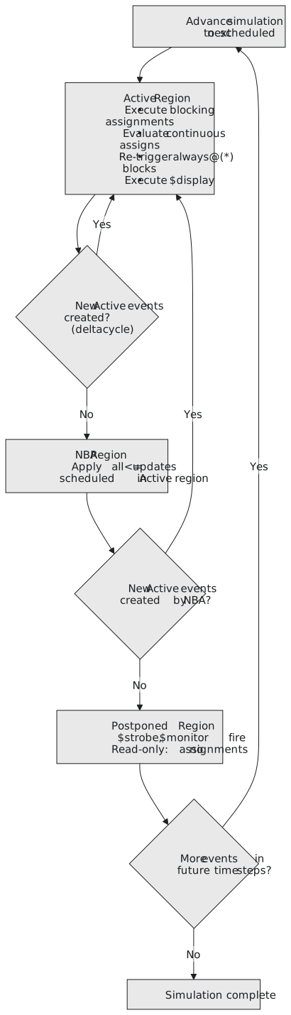
The standard describes each time step as a set of regions processed in order. Three matter for RTL:
| Region | What runs there |
|---|---|
| active | blocking assignments, continuous assigns, $display, port propagation, re-triggered always @(*) blocks |
| non-blocking | the left-hand-side updates from every <= evaluated in the active region |
| postponed | $strobe and $monitor, which only read |
Active first, then non-blocking, then postponed. If the non-blocking updates create new active events, the active region runs again in the same time step; that is a delta cycle. When nothing is left, time advances. SystemVerilog defines a dozen more regions for assertions and program blocks, and none of them matter here.
One edge, two flip-flops
`timescale 1ns / 1ps
`default_nettype none

module two_ff_chain (
    input  wire clk,
    input  wire d,
    output wire q2
);
    reg q1, q2_reg;

    always @(posedge clk) begin
        q1 <= d;
    end

    always @(posedge clk) begin
        q2_reg <= q1;
    end

    assign q2 = q2_reg;

endmodule
Start with d = 1, q1 = 0, q2_reg = 0, and let the edge fire. In the active region the simulator runs the two blocks in either order. First block first: read d, 1, schedule q1 := 1; read q1, still 0, schedule q2_reg := 0. Second block first: read q1, 0, schedule q2_reg := 0; read d, schedule q1 := 1. The same two updates either way, and the non-blocking region applies them: q1 = 1, q2_reg = 0. One stage per edge, regardless of order.
The same edge with the race
// wrong
always @(posedge clk) begin
    q1 = d;
end

always @(posedge clk) begin
    q2_reg = q1;
end
First block first: q1 becomes 1 immediately; the second block reads that 1; q2_reg = 1. Both stages moved in one edge. Second block first: q2_reg reads the old 0; then q1 becomes 1. Correct, by luck. Two legal orders, two behaviours, and nothing in the standard says which. It can change between simulators and between compile options of one simulator, and it is invisible until it is not.
Delta cycles
A delta cycle is the active region running again at the same time because something it did created a new event. Combinational logic does this all the time, harmlessly: an assign changes a wire, another assign that reads the wire re-evaluates, and so on until everything is stable, all at the same simulated instant. Feedback is the problem case:
assign b = ~a;
assign a = ~b;
Two inverters in a ring settle to one of two states, like the bistable of section 3.1. A ring with an odd number of inversions does not settle; the simulator iterates until it hits its limit and stops with a message about an infinite loop, and in silicon the same circuit is a ring oscillator. An always @(*) block that reads and writes the same signal is the same thing in a different costume.
Why $display lies
always @(posedge clk) begin
    q <= d;
    $display("q=%b d=%b", q, d);
end
$display runs in the active region, at the moment the <= is evaluated and before its update lands, so it prints the old q. $strobe runs in the postponed region, after the updates:
always @(posedge clk) begin
    q <= d;
    $strobe("q=%b after the update", q);
end
and prints the new one. $monitor is in the postponed region as well. When a $display in a clocked block seems a cycle behind, this is why; use $strobe, or print from the testbench after the edge.
The loop the simulator runs is in Figure 1.
What it explains
<= in clocked blocks: the updates go to the non-blocking region, so every block reads pre-edge values in the active region and the order is irrelevant.
= in combinational blocks: the block models a circuit that reacts to changes, the sequential order inside it is how intermediate results are built up, and since only one block ever writes a given signal, there is no ordering between blocks to worry about.
No mixing: mixed assignments put some updates in the active region and some in the non-blocking one, in an order that depends on the text, and no hardware corresponds to that.
When a sequential simulation misbehaves, the first question is whether there is a = in a clocked block. It usually is.
Practice Exercise
`timescale 1ns / 1ps
`default_nettype none

module trace_me (
    input  wire       clk,
    input  wire [3:0] d,
    output reg  [3:0] q1,
    output reg  [3:0] q2
);
    always @(posedge clk) begin
        q1 <= d;
    end

    always @(posedge clk) begin
        q2 <= q1;
    end

endmodule
Start from q1 = 0, q2 = 0. d becomes 4'hB just before edge 1 and stays there. List the events in the active and non-blocking regions of edges 1 and 2, and the values after each.
Solution
Edge 1, active: block 1 reads d = B, schedules q1 := B; block 2 reads q1 = 0, schedules q2 := 0; either order. Non-blocking: apply both. After edge 1, q1 = B, q2 = 0.
Edge 2, active: block 1 reads d = B, schedules q1 := B; block 2 reads q1 = B, since edge 1’s update landed long ago, schedules q2 := B. Non-blocking: apply. After edge 2, q1 = B, q2 = B.
The “reads see old values” rule is about one time step. Between edges, time advances and the updates are simply the values.
That is section 5.1: concurrency, always against initial, the two assignments and the scheduler behind them. The next section is about the part of an always block this section has taken for granted: what goes inside the @(...), and what happens when it is wrong.