The State Machine in RTL
Section 3.3 built state machines the long way: diagram, table, equations, gates. This section builds the same machines in Verilog, and the thing to hold onto is that nothing about the machine has changed. The flip-flops, the next-state logic and the output logic are the circuits you designed then; only the notation is different, and the synthesiser derives the gates.
Three circuits
Every state machine, whatever its size, encoding or type, is three pieces of hardware (Figure 1).

The state register is flip-flops holding the current state, loading the next state at each edge. It is always a clocked block:
always @(posedge clk or negedge rst_n) begin
    if (!rst_n)
        state <= IDLE;
    else
        state <= next_state;
end
Its width depends on the encoding: two bits for four states in binary, four bits in one-hot.
The next-state logic is combinational: from the current state and the inputs, where to go at the next edge.
always @(*) begin
    next_state = state;      // default: stay
    case (state)
        IDLE:    if (start) next_state = ACTIVE;
        ACTIVE:  if (done)  next_state = DONE;
        DONE:               next_state = IDLE;
        default:            next_state = IDLE;
    endcase
end
The default before the case is the latch-prevention habit of section 5.2, and it also means that any arm which does not change the state holds it.
The output logic is where Moore and Mealy part. A Moore output is a function of the state alone:
always @(*) begin
    active_led = (state == ACTIVE);
    done_led   = (state == DONE);
end
A Mealy output is a function of the state and the inputs, and can change between edges when an input changes:
always @(*) begin
    grant = (state == ARBITRATE) && req;
end
The distinction is only about what feeds the output block. Both machines have the same three circuits; a Moore machine simply has no wire from the inputs to the third.
Encodings
Before writing any block, give the states values, and do it with localparam, not parameter. A parameter can be overridden at instantiation, and a state machine whose encodings can be changed from outside is broken by construction.
localparam [1:0] IDLE   = 2'b00,
                 ACTIVE = 2'b01,
                 DONE   = 2'b10,
                 ERROR  = 2'b11;
Size them, [1:0], to match the state register, so that a width mismatch cannot be silently truncated.
Binary uses $\lceil \log_2 N \rceil$ flip-flops for $N$ states: fewest registers, and the next-state logic has to decode several bits, which makes it deeper. It is the usual choice for an ASIC, where a flip-flop is expensive.
One-hot uses one flip-flop per state, with exactly one set at a time:
localparam [3:0] RED    = 4'b0001,
                 GREEN  = 4'b0010,
                 YELLOW = 4'b0100,
                 PED    = 4'b1000;
More flip-flops, and “are we in GREEN” is state[1], one wire. On an FPGA, where flip-flops are plentiful and lookup-table inputs are the scarce thing, one-hot is often both smaller and faster.
Gray code, where consecutive states differ in one bit, saves switching power in a machine that steps through its states in a fixed order, and complicates the logic of one that does not. Section 3.3 covered the trade-offs at length.
For an FPGA, one-hot up to a dozen or so states; for an ASIC, binary; and the synthesiser can be told:
(* fsm_encoding = "one_hot" *) reg [3:0] state, next_state;
in Vivado’s syntax. Other tools have their own attribute; none is standard, and most tools will also choose for themselves if you let them.
Moore and Mealy in RTL
| Moore | Mealy | |
|---|---|---|
| output depends on | state | state and inputs |
| output changes | after the edge that changes state | as soon as an input changes |
| glitches | none, it comes from registers | possible, it is combinational from inputs |
| states | more, the output is in the state | fewer, the output is on the arc |
Moore is the default for the reasons section 3.3 gave: outputs come from registered state, cannot glitch, and are easy to pipeline. Mealy is for the case where the output must respond in the same cycle as the input that causes it, a zero-latency acknowledge for instance. Either way the output block is always @(*); a manual sensitivity list that omits an input in a Mealy block is the mismatch of section 5.2.
Practice Exercise
For the pedestrian traffic-light controller in Figure 2:
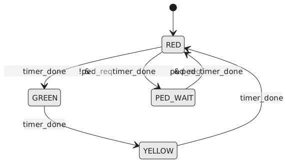
- How many flip-flops in binary, and in one-hot?
- Write the
localparamdefinitions for binary. - Which signals feed the next-state logic?
- Which feed the output logic for the Moore outputs
red,green,yellow,walk? - A
hurryoutput is high in GREEN when across_trafficinput is asserted. Moore or Mealy, and what does it depend on?
Solution
-
Four states: two flip-flops in binary, four in one-hot.
localparam [1:0] RED      = 2'b00,
                 GREEN    = 2'b01,
                 YELLOW   = 2'b10,
                 PED_WAIT = 2'b11;

reg [1:0] state, next_state;
-
state,timer_done,ped_req,ped_timer_done. -
stateonly. -
Mealy: it depends on
stateandcross_traffic.assign hurry = (state == GREEN) && cross_traffic;
The three circuits can be arranged over one, two or three always blocks, and the next three articles are those three styles.