Pipeline Registers
A combinational path takes 8 ns to settle and the clock period is 5 ns. The flip-flop at the end samples before the logic has finished, which is a setup violation, and it captures a wrong answer with complete confidence. There are two ways out: slow the clock to 8 ns, or cut the path into pieces that each fit in 5 ns, with a register between them. The second is pipelining, and it is how designs reach their clock targets.
The trade
One worker who does every step of a job takes 8 hours per item. Four stations of 2 hours each finish an item every 2 hours once the line is full, four times the rate, and each item still spends 8 hours in the line. No item got faster; many items together did.
Throughput, results per unit time, goes up: one per clock once the pipeline is full, with the clock now set by the longest stage rather than the whole path. Latency, cycles from an input to its result, goes up: $N$ cycles for $N$ stages. You do not get both, and pipelining is the bet that a faster clock on a steady stream matters more than the delay on any one result.
A two-stage multiply-add
A multiply followed by an add is a long path. Split it:
// stage 1: the product
always @(posedge clk) begin
    product_s1 <= a * b;
end

// stage 2: the sum
always @(posedge clk) begin
    result_s2 <= product_s1 + accum;
end
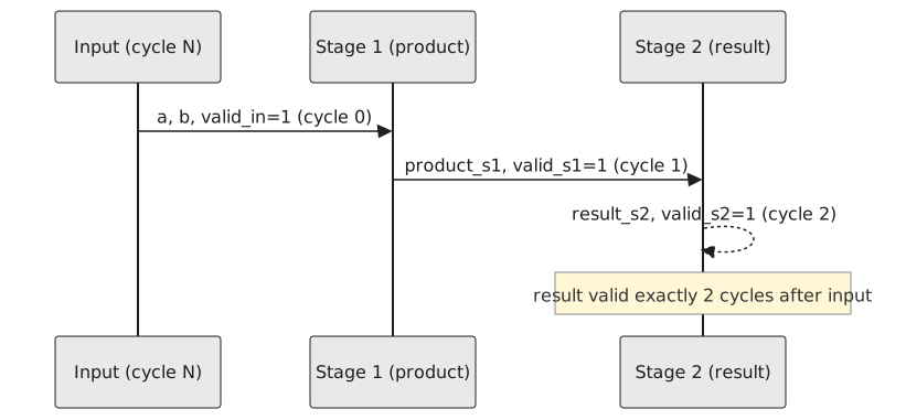
An input applied in cycle 0 has its product registered at cycle 1 and its sum at cycle 2: two cycles of latency. But a second input applied in cycle 1 has its product at cycle 2, while the first input’s sum is also landing at cycle 2. The two overlap. Once the pipeline is full, a result comes out every cycle, each one two cycles after its input.
What is in the pipeline
During reset, and for the first cycles after it, product_s1 and result_s2 hold values nobody asked for. A valid bit travelling with the data says which stage contents mean anything:
always @(posedge clk) begin
    valid_s1 <= valid_in;
    valid_s2 <= valid_s1;
end
It is the data path again, one bit wide. Each cycle the bit moves one stage, in step with the data, and when result_s2 is read, valid_s2 says whether it is a result or leftover (Figure 1).
What it does not do
This pipeline cannot stop. If whatever consumes result_s2 is not ready every cycle, nothing here can hold the earlier stages; data keeps coming whether or not it is caught. Real pipelines add a ready signal flowing backwards and hold logic at each stage, which is a subject of its own in Module 7. Everything here assumes a consumer that takes a result every cycle.
Timing closure on an FPGA is largely a pipelining exercise. When a design misses its clock, the usual fix is a register at a well-chosen point on the longest path, and knowing pipelines at this level is what makes a timing report readable.
Practice Exercise
A three-input adder sums three 8-bit numbers in one combinational block. Restructure it as a two-stage pipeline, say on which cycle each intermediate and the result become valid, and test that the value appears on exactly that cycle.
Solution
`timescale 1ns / 1ps
`default_nettype none

module adder_tree_pipelined (
    input  wire       clk,
    input  wire [7:0] a, b, c,
    input  wire       valid_in,
    output reg  [8:0] sum_out,
    output reg        valid_out
);
    reg [8:0] ab_s1;
    reg       valid_s1;

    always @(posedge clk) begin          // stage 1: a + b
        ab_s1    <= a + b;
        valid_s1 <= valid_in;
    end

    always @(posedge clk) begin          // stage 2: + c
        sum_out   <= ab_s1 + c;
        valid_out <= valid_s1;
    end
endmodule

module tb_adder_tree_pipelined;
    reg        clk = 0, valid_in;
    reg  [7:0] a, b, c;
    wire [8:0] sum_out;
    wire       valid_out;

    adder_tree_pipelined dut (.clk(clk), .a(a), .b(b), .c(c), .valid_in(valid_in), .sum_out(sum_out), .valid_out(valid_out));

    always #5 clk = ~clk;

    initial begin
        $dumpfile("tb.vcd");
        $dumpvars(0, tb_adder_tree_pipelined);

        valid_in = 0; a = 0; b = 0; c = 0;
        @(negedge clk);

        a = 8'd10; b = 8'd20; c = 8'd30; valid_in = 1;
        @(negedge clk);        // after edge 1: ab_s1 = 30, valid_s1 = 1
        valid_in = 0;
        @(negedge clk);        // after edge 2: sum_out = 60, valid_out = 1

        if (sum_out !== 9'd60 || valid_out !== 1'b1)
            $display("FAIL: sum_out=%0d valid_out=%b (expected 60, 1)", sum_out, valid_out);
        else
            $display("PASS: sum_out=%0d on cycle 2", sum_out);

        $finish;
    end
endmodule
The check is not only that the sum is 60 but that it is 60 on the second edge and not before, when ab_s1 alone is there.
Note that c is added in stage 2 to the value of a + b from stage 1, so c has to be held one cycle, or registered alongside ab_s1; in this test it is held, and in a real design you would register it.
That closes the register section. Section 5.6 puts the whole module together into the most important structure in digital design: the state machine, in RTL.