Loops as Hardware Generators
The way to make the loop-as-replicator idea stick is to build things with it. Here are four circuits every digital engineer ends up writing, each cleaner with a loop than by hand, and each showing a different side of the pattern.
Gray code encoder
Section 3.5 used Gray code for counters that cross clock domains: consecutive values differ in one bit. The encoding rule is
$$G_{N-1} = B_{N-1}, \qquad G_i = B_{i+1} \oplus B_i \ \text{for } i < N-1$$
`timescale 1ns / 1ps
`default_nettype none

module bin_to_gray #(
    parameter N = 8
) (
    input  wire [N-1:0] bin_in,
    output reg  [N-1:0] gray_out
);

    integer i;

    always @(*) begin
        gray_out[N-1] = bin_in[N-1];
        for (i = N - 2; i >= 0; i = i - 1) begin
            gray_out[i] = bin_in[i+1] ^ bin_in[i];
        end
    end

endmodule
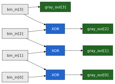
For $N = 4$ that unrolls to three XOR gates and one wire (Figure 1). Change $N$ to 16 and it is fifteen gates and a wire, with no chance of the off-by-one that hand-written indexing invites.
A testbench can check the defining property directly, that consecutive outputs differ in exactly one bit:
integer     t;
reg [N-1:0] prev_gray, diff;

initial begin
    for (t = 0; t < (1 << N); t = t + 1) begin
        bin_in = t[N-1:0];
        #10;
        if (t > 0) begin
            diff = gray_out ^ prev_gray;
            if (diff == 0 || (diff & (diff - 1)) != 0)     // zero bits or more than one bit changed
                $display("FAIL at %0d: diff=%b", t, diff);
        end
        prev_gray = gray_out;
    end
end
diff & (diff - 1) clears the lowest set bit, so it is zero exactly when diff has one bit set.
Leading-zero counter
Floating-point normalisation and priority arbitration both need the position of the highest set bit. Scan from the top; the first 1 is the answer.
`timescale 1ns / 1ps
`default_nettype none

module leading_zero_count #(
    parameter N = 8
) (
    input  wire [N-1:0]       data_in,
    output reg  [$clog2(N):0] lzc_out,     // 0 to N, so one bit more than clog2(N)
    output reg                all_zero
);

    integer i;
    reg     found;

    always @(*) begin
        lzc_out  = {($clog2(N)+1){1'b0}};
        all_zero = 1'b0;
        found    = 1'b0;

        for (i = N - 1; i >= 0; i = i - 1) begin
            if (!found && data_in[i]) begin
                lzc_out = N - 1 - i;
                found   = 1'b1;
            end
        end

        if (!found) begin
            lzc_out  = N;
            all_zero = 1'b1;
        end
    end

endmodule
The tool cannot stop the loop early; it unrolls all $N$ steps. The found flag makes every step after the first hit a no-op, and the hardware is a chain of muxes in which the first hit holds its value against all later ones: a priority encoder, with the priority coming from the direction of the loop. Run it upwards and you have a trailing-zero counter.
Bit reversal
`timescale 1ns / 1ps
`default_nettype none

module bit_reverse #(
    parameter N = 8
) (
    input  wire [N-1:0] data_in,
    output reg  [N-1:0] reversed
);

    integer i;

    always @(*) begin
        for (i = 0; i < N; i = i + 1) begin
            reversed[i] = data_in[N-1-i];
        end
    end

endmodule
Unrolled, this is reversed[0] = data_in[7], reversed[1] = data_in[6], and so on: eight wires, no gates. Bit-reversed addressing in an FFT, the permutations in a block cipher, and the swap between MSB-first and LSB-first serial formats all cost nothing but routing. A “computation” that takes $N$ memory accesses in software is free in silicon, which is one of the sharper differences between the two ways of thinking.
Equality comparator
`timescale 1ns / 1ps
`default_nettype none

module eq_compare #(
    parameter N = 8
) (
    input  wire [N-1:0] a,
    input  wire [N-1:0] b,
    output reg          equal
);

    integer i;
    reg     mismatch;

    always @(*) begin
        mismatch = 1'b0;
        for (i = 0; i < N; i = i + 1) begin
            mismatch = mismatch | (a[i] ^ b[i]);
        end
        equal = ~mismatch;
    end

endmodule
$N$ XOR gates into an OR tree and an inverter, which is what == builds. Write == in practice; the loop shows the structure.
A testbench for the leading-zero counter
`timescale 1ns / 1ps
`default_nettype none

module tb_lzc;

    localparam N = 4;

    reg  [N-1:0]       data_in;
    wire [$clog2(N):0] lzc_out;
    wire               all_zero;

    leading_zero_count #(.N(N)) u_dut (.data_in(data_in), .lzc_out(lzc_out), .all_zero(all_zero));

    initial begin
        $dumpfile("tb_lzc.vcd");
        $dumpvars(0, tb_lzc);
    end

    function automatic [$clog2(N):0] ref_lzc;     // the reference model
        input [N-1:0] d;
        integer k;
        begin
            ref_lzc = N;
            for (k = N - 1; k >= 0; k = k - 1) begin
                if (d[k] && ref_lzc == N)
                    ref_lzc = N - 1 - k;
            end
        end
    endfunction

    integer test, fail_count;

    initial begin
        fail_count = 0;

        for (test = 0; test < (1 << N); test = test + 1) begin
            data_in = test[N-1:0];
            #10;

            if ((data_in == 0) !== all_zero) begin
                $display("FAIL all_zero: data=%b got=%b", data_in, all_zero);
                fail_count = fail_count + 1;
            end

            if (lzc_out !== ref_lzc(data_in)) begin
                $display("FAIL lzc: data=%b expected=%0d got=%0d", data_in, ref_lzc(data_in), lzc_out);
                fail_count = fail_count + 1;
            end
        end

        if (fail_count == 0)
            $display("PASS: all %0d vectors.", 1 << N);
        else
            $display("FAIL: %0d failures.", fail_count);

        $finish;
    end

endmodule
The reference function is the same algorithm written for the simulator, and the test compares the two on every input. That is the pattern of the comparator testbench in section 4.5 and of most verification: a model beside the design, and a check that they agree. Exhaustive testing is practical to about twenty input bits; beyond that, directed and random tests take over.
The pattern
When the same operation applies to every bit, or every pair of adjacent bits, a parameterised for is the tool: the body says what happens at one position and the parameter says how many positions there are. Ask whether the operation is the same at each position, whether neighbouring bits share information as in parity and Gray code, whether there is a priority as in the leading-zero counter, and whether the answer is a function of the present inputs at all. If it needs state across cycles, it is a register, and section 5.5 is about those.
The next article is about the other loop that shares the keyword: generate, which repeats structure rather than computation.