Everything Runs at Once
What does this module do?
`timescale 1ns / 1ps
`default_nettype none

module mystery (
    input  wire a,
    input  wire b,
    output reg  x,
    output reg  y
);
    always @(*) begin
        x = a & y;
    end

    always @(*) begin
        y = b | x;
    end

endmodule
If your reading is “the first block runs and computes x, then the second block runs and computes y from it”, you are reading a hardware description as a program, and it will not tell you the truth.
The reflex
C, Python and Java all promise that line N finishes before line N+1 starts. There is an instruction pointer; concurrency is something you add on top, with threads, and it is hard precisely because it breaks the promise.
Verilog makes no such promise. There is no instruction pointer. Everything is concurrent unless you do something to make it otherwise. The module above does not compute x and then y. It describes two gates, an AND and an OR, each feeding the other, which is a feedback loop: it settles to something or it oscillates, and either way that is a circuit, not a sequence of steps.
Three kinds of machine
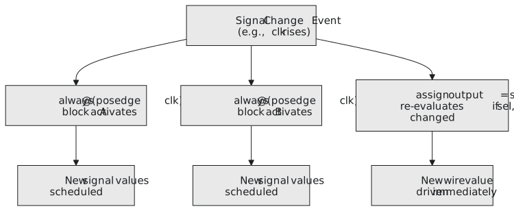
Every concurrent thing in a module is one of three:
- an
alwaysblock, which runs whenever something in its sensitivity list changes, and synthesises to gates or flip-flops; - an
assign, which re-evaluates whenever anything on its right changes, and is a wire with logic driving it; - a module instance, a whole sub-circuit with live wires on its ports.
In a module with ten blocks, five assigns and three instances, all eighteen are running (Figure 1). They respond to changes in whatever order the changes arrive, and nothing guarantees that any one of them runs before any other.
How the simulator does it
A simulator cannot model electrons. It models events. Time only advances when something changes, and everything that follows from that change is worked out before the clock moves on:
- Advance time to the next scheduled event.
- Find every process whose sensitivity list is satisfied by what changed.
- Run those processes, in some order the standard does not specify.
- Any new values they produce are new events; processes sensitive to them are scheduled for the same time step.
- Repeat until nothing is left for this time step, then advance.
“Some order the standard does not specify” is the important phrase. Real hardware has no order either: two gates that switch in the same nanosecond do not take turns. The consequence for you is that if two processes in the same time step write the same signal, or one reads with a blocking assignment what another writes with one, the result depends on the simulator. That is a race, and it is a bug in the design, not the simulator.
Back to the mystery
Trace it. With a = 1, b = 0, x = 0, y = 0, let b rise to 1. The second block runs: y = 1 | 0 = 1. That change triggers the first block: x = 1 & 1 = 1. That triggers the second again: y = 1 | 1 = 1, no change, and it settles at x = 1, y = 1. Now drop b to 0: y = 0 | x = 0 | 1 = 1, no change. It never comes back down. What you have built is a latch, held by the feedback through the AND and the OR, and it holds until a drops.
A combinational feedback loop that settles is a latch you did not ask for; one that does not settle is a ring oscillator, and the simulator will iterate until it hits a limit and gives up. The rule that avoids both is simple: a combinational block never writes a signal that feeds back into its own inputs, and combinational and sequential logic are kept in separate blocks.
The other race
Feedback is a design error. There is a subtler race in perfectly sensible sequential code. This is a two-stage shift register, written wrongly:
// wrong
always @(posedge clk) begin
    q1 = d;
end

always @(posedge clk) begin
    q2 = q1;
end
Both blocks fire on the same edge. If the simulator runs the first block first, q2 reads the new q1, which is d, and both stages advance in one cycle: the register collapses to a wire. If it runs the second first, q2 reads the old q1 and the register works. Same code, two behaviours, chosen by the simulator. The fix is the non-blocking assignment, <=, and the fourth article of this section is about exactly why it works. For now, take it as the reason the two rules in the module introduction exist: they are the cure for the race that concurrency creates.
Practice Exercise
For each block: is it synthesisable hardware or simulation only, and is it combinational, sequential or testbench?
`timescale 1ns / 1ps
`default_nettype none

module classify_me (
    input  wire clk,
    input  wire rst,
    input  wire d,
    output reg  q,
    output reg  parity
);
    // 1
    always @(posedge clk) begin
        if (rst)
            q <= 1'b0;
        else
            q <= d;
    end

    // 2
    always @(*) begin
        parity = q ^ d;
    end

    // 3
    initial begin
        $display("Simulation started");
    end

endmodule
Solution
Block 1 is a D flip-flop with synchronous reset: sequential, synthesisable. Block 2 is an XOR gate: combinational, synthesisable. Block 3 runs once at time zero and prints; initial and $display are simulation only and belong in a testbench.
The next article is about that third block: what initial is for, why it means nothing to a synthesiser, and the mistake of using it to set a register’s starting value.