Reset
At power-up every flip-flop holds whatever the silicon settled into. A state machine can wake in an illegal state and a counter mid-count. Reset forces every register to a known value before anything trusts it. The goal is simple, and how to wire it has been argued about for as long as there have been RTL engineers. Section 3.2 covered the hardware side; this is the Verilog.
Synchronous
always @(posedge clk) begin
    if (!rst_n)
        q <= 1'b0;
    else
        q <= d;
end
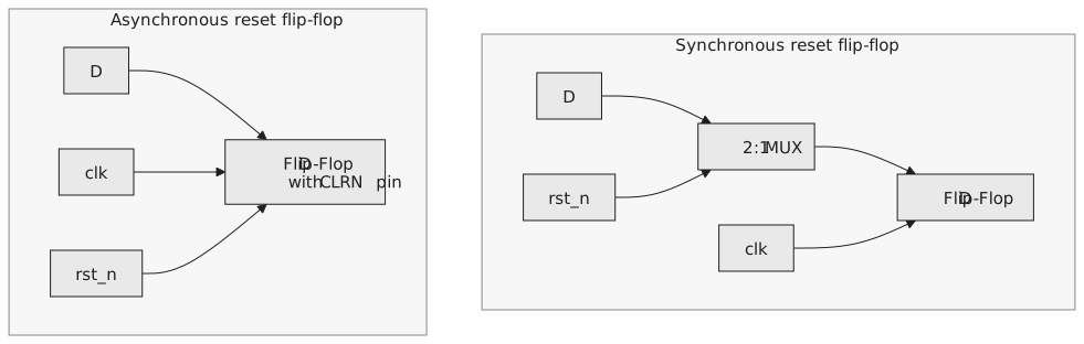
rst_n is not in the sensitivity list. The flip-flop only changes on a clock edge, reset included; the reset is a mux in front of D, choosing 0 when rst_n is low, and the mux is only looked at when the clock ticks. A glitch on the reset line between edges does nothing, which is a real advantage on a noisy board. The cost: the reset pulse has to be at least a clock period wide to be seen, and the mux is extra logic in front of every flip-flop.
Asynchronous
always @(posedge clk or negedge rst_n) begin
    if (!rst_n)
        q <= 1'b0;
    else
        q <= d;
end
Now rst_n is in the list and q clears the moment it falls, clock or no clock. At power-up, when the clock may not be running yet, that is what you want. Library flip-flops have an asynchronous clear pin, so this is usually cheaper in silicon than the mux, not dearer.
What it trades away is control of the release. rst_n rising is a signal transition like any other, and if it happens too close to a clock edge it violates setup on every flip-flop at once, and the design can come out of reset metastable on the first cycle it is meant to be working. Section 3.2 called this the reset-release problem.
Assert asynchronously, release synchronously
The way the industry settles it: keep the immediate assertion, and make the release land on a clock edge. A reset synchroniser is two flip-flops in series, fed a constant 1, with the raw reset on their asynchronous clear (Figure 1):
module reset_synchronizer (
    input  wire clk,
    input  wire async_rst_n,    // from the pin
    output wire sync_rst_n      // to the design
);
    reg [1:0] sync_ff;

    always @(posedge clk or negedge async_rst_n) begin
        if (!async_rst_n)
            sync_ff <= 2'b00;                   // assert: immediate
        else
            sync_ff <= {sync_ff[0], 1'b1};      // release: a 1 shifts through in two cycles
    end

    assign sync_rst_n = sync_ff[1];
endmodule
When the pin drops, both flip-flops clear at once and sync_rst_n goes low immediately. When the pin rises, a 1 takes two edges to reach the output, so the release is aligned to the clock, and if the first flip-flop goes metastable on a badly timed release it has a full cycle to settle before the second samples it. This is the two-flop synchroniser of section 3.2 with a different job. Everything downstream uses sync_rst_n and never the pin.
Active low
Every example uses rst_n, asserted at 0. Library flip-flops have active-low clear pins, so an active-low reset maps onto the cell with no inverter, and reset pins with pull-ups give an active-low signal for free. Active-high resets appear in FPGA-oriented code and older designs; default to active low unless something specific says otherwise, and never mix the two in one design.
For an ASIC, asynchronous reset with a synchroniser is the usual answer. For an FPGA, look at what the device’s flip-flops support; several families implement a synchronous reset more cheaply and the vendor’s guide will say so.
Practice Exercise
Write a 4-bit up-counter twice, with each reset style, simulate both with the reset released close to a clock edge, and see in GTKWave which cycle each starts counting on.
Solution
module counter_sync_rst (
    input  wire       clk, rst_n,
    output reg  [3:0] count
);
    always @(posedge clk) begin
        if (!rst_n) count <= 4'b0000;
        else        count <= count + 1'b1;
    end
endmodule

module counter_async_rst (
    input  wire       clk, rst_n,
    output reg  [3:0] count
);
    always @(posedge clk or negedge rst_n) begin
        if (!rst_n) count <= 4'b0000;
        else        count <= count + 1'b1;
    end
endmodule
In the waveform the asynchronous counter drops to 0 the instant rst_n falls, wherever the clock is. The synchronous one holds its value until the next rising edge and clears then, up to a period later. That gap is the whole practical difference, visible rather than described.
Next: registers that should not update on every edge, the enable pattern that handles it, and the clock-gating shortcut not to take.