The One-Process Style
Three circuits; how many blocks? The shortest answer is one.
Everything in one block
always @(posedge clk or negedge rst_n) begin
    if (!rst_n) begin
        state <= IDLE;
        out   <= 1'b0;
    end else begin
        case (state)
            IDLE: begin
                out <= 1'b0;
                if (start) state <= ACTIVE;
            end
            ACTIVE: begin
                out <= 1'b1;
                if (done) state <= IDLE;
            end
        endcase
    end
end
state and out are both assigned with <= in a clocked block, so both are flip-flops. The state register and every output are registered and change together at the edge.
What it gives
It is the least code. And because every output comes out of a flip-flop, none can glitch between edges, which matters when an output goes somewhere sensitive to glitches, such as into another clock domain through a synchroniser.
What it costs
Look at the IDLE arm. When start is seen, state goes to ACTIVE at this edge, and out is assigned 0 at this same edge, by the IDLE arm. out becomes 1 only at the next edge, when the ACTIVE arm runs. The output reflects the state the machine was in, not the one it is entering, and every output is one cycle late relative to the transition.
For a Moore output that is often fine. For a Mealy output that must respond in the same cycle as the input, the one-process style cannot do it; everything here is registered.
A detector
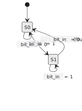
Detect the two-bit sequence 10 on a serial line and pulse found (Figure 1).
`timescale 1ns / 1ps
`default_nettype none

module packet_detector_1proc (
    input  wire clk, rst_n, bit_in,
    output reg  found
);
    localparam S0 = 1'b0, S1 = 1'b1;
    reg state;

    always @(posedge clk or negedge rst_n) begin
        if (!rst_n) begin
            state <= S0;
            found <= 1'b0;
        end else begin
            case (state)
                S0: begin
                    found <= 1'b0;
                    if (bit_in) state <= S1;
                end
                S1: begin
                    if (!bit_in) begin
                        found <= 1'b1;      // registered: seen the cycle after the 0 arrives
                        state <= S0;
                    end else begin
                        found <= 1'b0;
                        state <= S1;
                    end
                end
            endcase
        end
    end
endmodule

module tb_packet_detector_1proc;
    reg  clk = 0, rst_n, bit_in;
    wire found;

    packet_detector_1proc dut (.clk(clk), .rst_n(rst_n), .bit_in(bit_in), .found(found));
    always #5 clk = ~clk;

    integer   i;
    reg [4:0] stream = 5'b10100;     // 10 appears twice

    initial begin
        $dumpfile("tb.vcd");
        $dumpvars(0, tb_packet_detector_1proc);

        rst_n = 0; bit_in = 0;
        @(negedge clk); rst_n = 1;

        for (i = 4; i >= 0; i = i - 1) begin
            bit_in = stream[i];
            @(negedge clk);
            $display("t=%0t bit_in=%b state=%b found=%b", $time, bit_in, dut.state, found);
        end

        $finish;
    end
endmodule
In the printout found rises one cycle after the 0 that completes the pattern, because it is computed in the clocked block alongside the transition. That is the delay this article is about, in a trace rather than in prose.
Some engineers use this style by default precisely because registered outputs are what a clock-domain crossing wants. Others avoid it because the one-cycle lag catches readers out. Both conventions exist in production code; recognise the shape.
The next article is the style you will see most: the state register in one block and everything combinational in another.