Margining and Derating: Designing for the Worst Case You'll Actually See
In the previous article we said that ss_100C_1v60 and ff_n40C_1v95 represent the two ends of the manufacturing distribution. That statement has a quiet footnote, and this article is about it. Even on a single die that landed exactly at the slow corner, not every transistor is identical to every other. Corners handle variation from die to die. They do not, on their own, handle variation within one die, and that is what margining and derating are for.
Two kinds of variation
Die-to-die variation is what corners already model. Take a hundred chips from a production run and they spread from slower to faster than nominal, depending on how the process landed for each die.
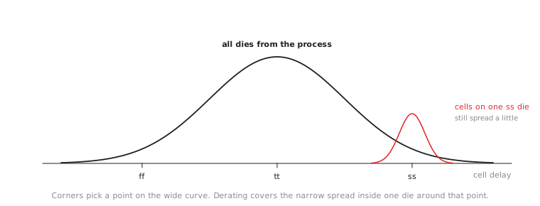
On-chip variation (OCV) is a second, separate effect. Even on one die, delay varies a little from place to place. Part of it is systematic, a gradual gradient across the die from uneven temperature or supply. Part of it is random, local transistor-to-transistor differences from the manufacturing process itself. A launching flop and a capturing flop a millimetre apart can each behave as if they were at a slightly different corner, even though a single Liberty file assumes every cell on the die behaves identically. Figure 1 shows the two scales.
Derating: a multiplier, not a new corner
Derating scales computed delays by a factor, to cover on-chip variation without a separate corner, or an impossibly expensive Monte Carlo simulation, for every combination of locally fast and locally slow cells. OpenSTA supports it directly:
% set_timing_derate -late 1.05
% set_timing_derate -early 0.95
Without further options, these apply to both cell and net delays. For a setup check, the tool uses the -late factor on the launching clock path and the data path, making them look 5% slower, and the -early factor on the capturing clock path, making it look 5% faster. Both directions squeeze the check. For a hold check the roles swap. The idea is simple: assume the cells that hurt you are a little slower, and the ones that help you a little faster, than the Liberty file says.
The factors above, 5% each way, are illustrative for this article, not a SKY130 or OpenLane default. Real derating factors come from the process’s characterised variation data and the design team’s risk tolerance. More advanced methods (AOCV, POCV) vary the factor with path depth and distance, because random variation partly averages out over long paths. The simple flat factor is enough to show the effect.
Applying derating to our path
Recall the closed parity path at the slow corner from Section 7.4, passing at +0.14 ns with an arrival time of 3.42 ns and a required time of 3.56 ns. The clock latency on this path is shown as zero, so only the data path is affected. Derating its delay by 5%:
$$\text{Derated arrival} = 3.42 \times 1.05 \approx 3.59\ \text{ns}$$
Against the same 3.56 ns required time, the slack is now about −0.03 ns. A modest, standard margin assumption, applied on top of a corner result that passed, has pushed the path back into a (small) failure.
This is exactly why the ECO in Section 7.4 was given a margin (-setup_margin 0.1) instead of closing the violation to zero. A fix that closes to 0.00 ns at the corner level has nothing left once derating is applied. As it turns out, even 0.1 ns was not quite enough for a 3.4 ns path, since 5% of 3.42 ns is 0.17 ns. A robust closure needs corner-level margin at least as large as whatever derating will take away.
A mistake to avoid is applying derating only to the paths you are already worried about. In a real signoff run the derating factors are set once, as part of the STA setup, and apply to every path. Derating selectively defeats the purpose, which is to catch problems on the paths nobody was worried about.
Practice Exercise
A path passes at the tt corner with +0.85 ns of slack and no derating. Its arrival time is 1.70 ns, of which 1.10 ns is cell delay and 0.60 ns is wire delay, with no clock latency. Apply a 5% late derate to the whole data path. Does it survive, and with how much margin?
Solution
The required time is 1.70 + 0.85 = 2.55 ns. The derated arrival is 1.70 × 1.05 = 1.785 ns. The new slack is 2.55 − 1.785 ≈ +0.77 ns.
The path survives easily, losing only about 0.085 ns. Compare this with the parity path, whose thin +0.14 ns could not absorb the 0.17 ns that the same 5% took from it. Derating does not threaten every path equally. It threatens long paths, which lose more in absolute terms, and paths that were already close to the edge. Those are the paths a signoff review should look at hardest.
In the next article, the last of this module, we put corners, ECOs and derating together and run the complete multi-corner signoff timing pass on the UART.