Buffer Insertion and Gate Sizing as ECO Techniques
In the previous article we decided the parity path needs an ECO, not a rerun. In this article we look at the two techniques that cover most real ECO fixes, and apply the reasoning to parity_net. Both follow directly from what we found in its SPEF in Section 7.2: the wire’s own RC is only a few picoseconds, and the delay is the XOR _2204_ charging 118.6 fF.
Gate sizing: make the driver stronger
Gate sizing replaces a cell with a stronger or weaker version of the same function. Here that means swapping _2204_ from sky130_fd_sc_hd__xor2_2 to sky130_fd_sc_hd__xor2_4. A higher drive strength means wider transistors and a lower output resistance, so the same load charges faster.
Sizing has limits. The HD library’s XOR stops at xor2_4. A bigger cell also has a bigger input capacitance, which loads the gate before it (_2203_ in our path) and slows that stage down a little. And an XOR is a relatively poor driver for its size, because its output goes through stacked transistors. For a small or moderate load, upsizing alone is often enough. For a load as large as parity_net’s it helps, but it cannot do the whole job.
Buffer insertion: take the load off the weak gate
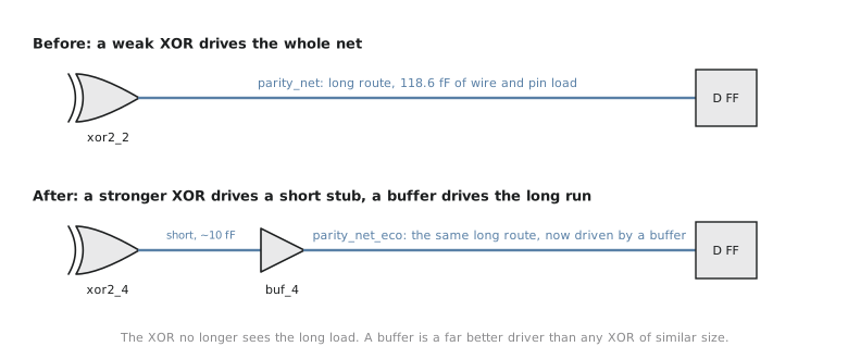
Buffer insertion places a buffer cell on the net and splits it in two. The original driver now charges only a short stub and the buffer’s input pin. The buffer, which is built as two inverters and is an efficient driver, charges the long remainder of the route.
For a net like parity_net, where the problem is a big capacitance on a weak gate, the buffer goes near the driver, so that almost all the capacitance moves onto the buffer. On very long, resistive routes, buffers are also placed partway along the wire. There, as we saw with the Elmore sum in Section 7.2, splitting the wire stops the resistance near the far end from having to charge everything downstream, and it keeps the signal edges sharp. For the UART’s routes the load effect is the one that matters.
The buffer adds its own delay, a few hundred picoseconds at the slow corner, but that is small compared with what it saves when the original stage was taking nearly three nanoseconds.
The tradeoffs
Neither technique is free. A real ECO weighs these costs against the size of the violation:
| Tradeoff | Buffer insertion | Gate sizing |
|---|---|---|
| Area | A new cell, plus a site to place it and routing to it | The larger cell is wider, so legalisation may nudge its neighbours |
| Power | Extra switching at the buffer | Larger transistors switch more charge, and the bigger input loads the previous stage |
| Risk | Changes arrival times downstream, which can erode hold margin; needs placement and routing space nearby | Slows the previous stage and any other nets it drives |
It is tempting to think a bigger fix is always a safer one. Both techniques can fix the targeted violation and create a new one elsewhere. A new buffer changes the arrival time at every flop downstream, and a faster path is closer to a hold violation at the fast corner. This is why every ECO must be followed by a fresh check at every corner and mode that matters, not only the one the fix was aimed at.
When real fixes combine both
For parity_net, long and heavily loaded with a driver that is small for that load, the most effective fix combines both: upsize _2204_ so it charges its short stub quickly, and insert a buffer right after it so the XOR no longer sees the long route at all. Figure 1 shows the before and after.
In practice engineers rarely choose by hand which technique goes on which net. That is the job of OpenROAD’s repair_timing, which we use in the next article. It tries combinations of buffering and sizing on every violating path, within area and utilisation limits. Understanding the two techniques separately is what lets you read what an automated repair did and judge whether its choices make sense.
Practice Exercise
Two nets both violate at the slow corner by about the same amount. Net A is short, with three nearby loads totalling 25 fF, driven by a nand2_1. Net B is a long route with one far-away load and 110 fF in total, driven by an xor2_2, much like parity_net. A repair run with only gate sizing allowed (no buffering) closes net A completely but only partly recovers net B. Explain why.
Solution
For net A the whole problem is a small cell driving a moderate load. The NAND family in the HD library goes up to much stronger versions than nand2_1, so swapping in one with several times the drive fixes the delay, and the extra input capacitance on the previous stage is a small price.
For net B the load is several times larger and the driver is an XOR, which only goes up to xor2_4 and is a weaker driver than a simple gate of the same size. Upsizing helps, but even the largest XOR is still slow with 110 fF on its output, and the bigger XOR also loads the stage before it. The resistance of the wire is not the issue. What net B needs is to move the load onto a cell designed to drive it, which is exactly what a buffer does. Sizing alone can only partly compensate.
In the next article we apply both techniques to the real parity-path violation with repair_timing, and check the corrected report.