Reading a SPEF File
In the previous article we looked at what extraction computes. In this article we read the file it writes. The first time you open a real SPEF it looks like a wall of asterisks, underscores and decimal numbers. It is actually one of the most literal formats in the whole flow: net by net, it lists every resistor and capacitor that net turned out to have, with nothing layered on top. Once you know its sections you can read any SPEF in this course.
The sections
- Header. Design name, the tool that wrote the file, the characters used as hierarchy divider and pin delimiter, and the units every number below is expressed in (time, capacitance, resistance, inductance).
*NAME_MAP. A table that maps short indices like*12to full net and instance names, so the rest of the file does not repeat long hierarchical names thousands of times.*PORTS. The design’s top-level pins, listed once.*D_NETblocks. One per net, each containing:*CONN, the pins on this net.*Imarks an instance pin and*Pa top-level port, and the letter after the pin name gives its direction:Ofor the pin that drives the net,Ifor a pin that loads it.*CAP, the capacitance at each node of the net. A node is a point where the route branches, changes layer, or meets a pin.*RES, the resistance between pairs of nodes. This is what turns the net from one lumped capacitor into an RC network with its own internal delay.
A real excerpt: parity_net
Here is the SPEF entry for the net this module has been following, the output of the parity XOR tree on its way to the parity-error flop. The header is included once so you can see the units:
*SPEF "IEEE 1481-1999"
*DESIGN "uart_top"
*DATE "2026-09-14 10:14:02"
*VENDOR "OpenROAD"
*PROGRAM "OpenRCX"
*VERSION "1.0"
*DESIGN_FLOW "NAME_SCOPE LOCAL"
*DIVIDER /
*DELIMITER :
*BUS_DELIMITER [ ]
*T_UNIT 1 NS
*C_UNIT 1 FF
*R_UNIT 1 OHM
*L_UNIT 1 HENRY

*NAME_MAP
*1 rx_ctrl/parity_net
*2 rx_ctrl/_2204_
*3 rx_ctrl/parity_err_reg

*D_NET *1 118.6
*CONN
*I *2:X O
*I *3:D I
*CAP
1 *2:X 9.4
2 *1:1 14.1
3 *1:2 11.8
4 *3:D 83.3
*RES
1 *2:X *1:1 6.2
2 *1:1 *1:2 18.9
3 *1:2 *3:D 41.7
*END
Reading it from the top:
- The header gives the units: nanoseconds, femtofarads, ohms. Always check this first. Some tool setups write picofarads or kilo-ohms, and misreading the unit is the easiest way to be wrong by three orders of magnitude.
- The name map says
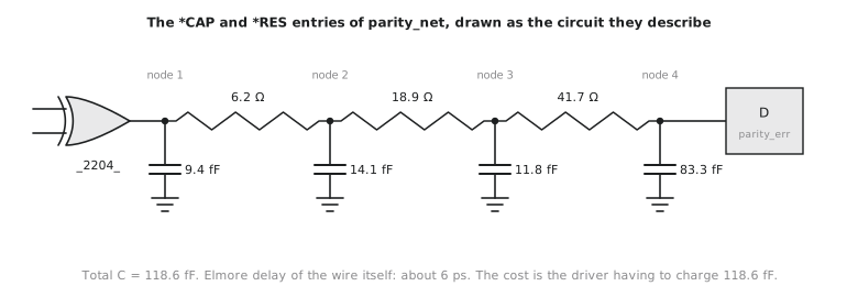
*1isrx_ctrl/parity_net,*2is the XOR instance_2204_and*3is the flopparity_err_reg. The header declared:as the pin delimiter, so*2:Xmeans pin X of_2204_. *D_NET *1 118.6names the net and gives its total capacitance, 118.6 fF.*CONNlists two pins.*2:X Ois the XOR output, which drives the net.*3:D Iis the flop’s D input, which loads it. The direction letter describes the pin’s role, not the net’s.*CAPlists four nodes: the driver pin, two internal points along the route (*1:1and*1:2), and the load pin. Their values are 9.4, 14.1, 11.8 and 83.3 fF. The sum, 118.6 fF, matches the total on the*D_NETline, which is a good sanity check whenever you read a SPEF by hand.*RESlists three resistors joining those nodes in a chain from driver to load: 6.2, 18.9 and 41.7 Ω.
Figure 1 draws the same entry as the circuit it describes.
Where the delay of this net comes from
The largest capacitance (83.3 fF) sits at the far end, at the flop’s D pin. In practice this is the long last stretch of the route, the part that crosses from the datapath area into the control logic, lumped onto the node where it ends. That is the detour Section 7.1 blamed for this net’s worse-than-estimated delay.
A quick way to see how much delay the wire itself adds is the Elmore delay: for each resistor, multiply it by all the capacitance downstream of it, and add up the products.
$$\tau_{wire} = 6.2 \times 109.2 + 18.9 \times 95.1 + 41.7 \times 83.3 \approx 5950\ \Omega \cdot \text{fF} \approx 6\ \text{ps}$$
Six picoseconds. The wire’s own RC is not where this net’s 1.95 ns went. What costs time is that the XOR has to charge all 118.6 fF through its own output resistance, which is kilo-ohms, not tens of ohms. This is the physical picture behind everything Section 7.4 does to fix this path: give the net a stronger driver, or take most of that capacitance off the weak XOR by putting a buffer in front of it.
Note also that the Elmore sum is dominated by the last term. Resistance close to the load, with a big capacitance after it, costs more than the same resistance near the driver with little after it. On a long, resistive route that position effect becomes significant, and it is one reason long nets get buffers partway along them.
A mistake worth avoiding is to read only the total on the *D_NET line. STA delay calculation uses the full *CAP and *RES network, because it needs both the load the driver sees and the slew and delay at each load pin. On a net with several loads at different distances the totals alone cannot tell you which load sees the slowest edge.
Practice Exercise
A different net has a total capacitance of 62.0 fF. Its three nodes are the driver pin (45.0 fF), an internal point (10.0 fF) and the load pin (7.0 fF), joined by 5.0 Ω and 12.0 Ω. Compute the Elmore delay of this wire and compare it with parity_net. Then say which of the two nets would gain more from upsizing its driver, and why.
Solution
Elmore delay = 5.0 × (10.0 + 7.0) + 12.0 × 7.0 = 85 + 84 = 169 Ω·fF, about 0.17 ps. Like parity_net, the wire itself is negligible.
For both nets the delay is set by how fast the driver can charge the total capacitance: 62 fF here, 118.6 fF for parity_net. Upsizing lowers the driver’s output resistance and helps both. It helps parity_net more in absolute terms, because it has almost twice the load. But there is a limit: a bigger XOR also has bigger input capacitance, which slows the stage before it, and SKY130’s HD library only goes up to xor2_4. For a load as large as parity_net’s, a buffer that takes over most of the capacitance is usually the better tool, which is exactly what Section 7.4 ends up doing.
Reading a SPEF by hand is useful, but the entry above came from somewhere. In the next article we run the extraction ourselves on the routed UART and pull this net out of the tool’s output.