PVT Corners and Multi-Corner Multi-Mode Analysis
In the previous article the parity path passed with 0.19 ns of slack. That is true, but only under one set of assumptions: this silicon, at this supply voltage, at this temperature. A real chip does not get to choose. A fabricated part can come out a little faster or slower than nominal from manufacturing variation, it can run hot or cold depending on where it lives, and its supply can sag under load. In this article we look at how signoff covers all of that.
The three axes
Process (P) covers manufacturing variation. No two wafers, and no two lots, produce transistors with exactly the same strength. The SKY130 standard cell library ships Liberty files characterised at several process corners, so you never model this yourself. You pick which characterised corner to analyse against.
Voltage (V) covers the supply. IR drop under switching load, regulator tolerance and plain margin all mean the voltage a cell sees can differ from the nominal supply.
Temperature (T) covers the operating environment. Cell delay changes with temperature, and a chip in a sealed box in the sun runs much hotter than the same chip on a lab bench.
A corner is one combination of all three. The sky130_fd_sc_hd library names its Liberty files after exactly that combination, for example:
| Liberty file | Process | Temperature | Supply |
|---|---|---|---|
sky130_fd_sc_hd__tt_025C_1v80.lib |
typical | 25 °C | 1.80 V (nominal) |
sky130_fd_sc_hd__ss_100C_1v60.lib |
slow NMOS, slow PMOS | 100 °C | 1.60 V |
sky130_fd_sc_hd__ff_n40C_1v95.lib |
fast NMOS, fast PMOS | −40 °C | 1.95 V |
The characterisation inside each file is the PDK’s own data, not something to memorise. What matters is the pattern the names encode, and why all three get checked. Figure 1 shows how much the same two cells from our path change between them.
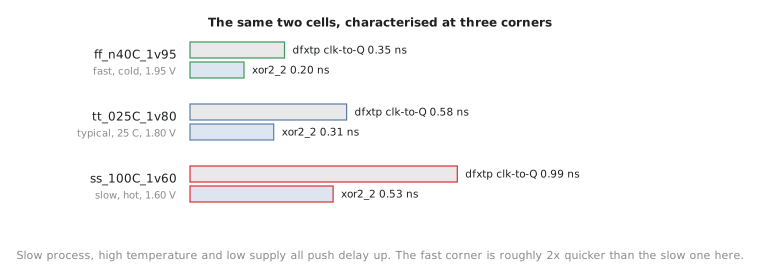
Look at which direction makes cells slow. Slow process, high temperature and low voltage all push delay up, which is why ss_100C_1v60 is the usual worst case for setup. Fast process, low temperature and high voltage all push delay down, so ff_n40C_1v95 is the fastest a real part is expected to run. That turns out to matter a great deal for hold, as Section 7.5 explains.
One more detail. In a modern process like SKY130, the combination of low temperature and low voltage can sometimes be slower than high temperature, an effect called temperature inversion. That is one reason large signoff flows check more corners than these three. For this course the three above are enough.
Why typical is not signoff
The previous report used tt_025C_1v80, the middle of the distribution and the corner every earlier module used by default. It is a sensible corner to develop against because it represents an average part. But it does not represent the worst part in a real production population, and a design that only meets timing at the average will fail on some fraction of the chips that come back.
Modes on top of corners
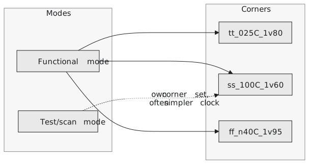
Corners assume the design only ever works one way. Real chips often have genuinely different modes: different clock setups or functional states, each with its own timing requirements and sometimes its own set of corners. The classic example is functional mode, where the chip runs its normal clock and datapath, and test mode, where a scan chain shifts data through every flop at a (usually much slower) test clock. A path that matters in functional mode may not matter in test mode and the other way round. The scan-mux path from the exercise in Section 7.1 is exactly this kind of mode-dependent path.
Multi-corner multi-mode (MCMM) analysis means checking every relevant mode at every corner relevant to that mode, the full cross product that a real signoff has to clear. Figure 2 shows the idea for two modes. The UART in this course keeps things manageable by checking functional mode at the three corners above. A commercial signoff on a larger chip can check several modes at five or more corners each.
A common mistake is to check only the slow corner and consider the job done. Setup violations are indeed worst at the slow corner. Hold violations do not depend on the clock period at all and are usually worst at the fast corner, where data races through the logic quickest. Skip the fast corner and a hold violation can pass through signoff unnoticed until first silicon.
Practice Exercise
A design passes setup comfortably at ss_100C_1v60 and at tt_025C_1v80, but has never been checked at ff_n40C_1v95. A teammate says that is fine, because the slow corner is the hard one for setup and it passed. What check is missing, and why is it a real gap and not a redundant one?
Solution
The missing check is hold at the fast corner. Setup (Path Type: max) gets harder when delay is large, so ss_100C_1v60 really is the hard case for setup and passing there means something. Hold (Path Type: min) is a minimum-delay check: it fails when data changes too soon after the capturing edge, which is most likely when the logic is fastest, at the fast, cold, high-voltage corner. A design that was only checked at the slow corner could have a real hold violation at the fast corner and nobody would know until parts from the fast end of the process came back. It is a different failure mode that only shows at the other end of the range, not a repeat of a check already done.
In the next article we stop talking about corners and run all three on the UART, and compare the parity path at each one, including the corner where it fails.