The Corners SKY130 Designs Are Actually Signed Off Against
In Section 7.4 we closed the parity-path violation and re-checked it at three corners. In this last section we put everything together for signoff. Before running the final pass, I want to be precise about why these particular three corners, tt_025C_1v80, ss_100C_1v60 and ff_n40C_1v95, and which failure each one protects against. Signoff is not “check a few corners and hope”. It is a small, deliberate set, chosen because each member is the worst case for a particular check.
Typical, fast and slow
Every corner name in the sky130_fd_sc_hd library encodes a process letter pair, a temperature and a voltage:
tt, typical process. An average die, in the middle of the expected process distribution. This is the everyday development corner, the one every earlier module in this course used by default.ss, slow-slow. A die from the slow end of the distribution for both NMOS and PMOS (hence two letters). Combined with high temperature and low supply, it is close to the slowest a real part is expected to be.ff, fast-fast. The opposite: fast NMOS and PMOS, low temperature and high supply, close to the fastest a real part is expected to be.
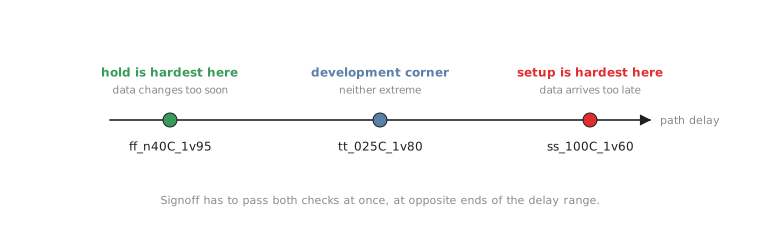
How far apart these corners are in numbers is the PDK’s characterisation data, not something to guess. For signoff strategy what matters is the ordering in Figure 1: ss at the slow end, ff at the fast end, tt in between, and a different check at each end.
Why setup lives at the slow corner
Recall the setup inequality from Section 7.1:
$$T_{clk} \geq t_{clk\text{-}to\text{-}Q} + T_{comb} + t_{setup}$$
A setup violation happens when the right-hand side grows too large for the clock period, so setup gets worse whenever cell and wire delays get larger. Slow process, high temperature and low voltage all push delay up. That is why the parity path failed at ss_100C_1v60, and why real signoff always includes it: it is the condition most likely to expose a setup problem anywhere in the design.
Why hold lives at the fast corner
The hold inequality is
$$t_{clk\text{-}to\text{-}Q} + T_{comb} \geq t_{hold}$$
This fails when the left-hand side is too small, when data changes too soon after the capturing edge. Fast process, low temperature and high voltage all push delay down, which makes the left-hand side smaller and a hold violation more likely. It also explains the exercise in Section 7.3: a design only checked at the slow corner can have a real hold violation at the fast corner and never see it, because hold gets harder exactly where setup gets easier.
| Corner | Delay | Worst case for | Why |
|---|---|---|---|
ss_100C_1v60 |
pushed up | Setup | Longer delay makes the setup inequality harder to meet |
ff_n40C_1v95 |
pushed down | Hold | Shorter delay makes the hold inequality harder to meet |
tt_025C_1v80 |
nominal | Neither extreme | Everyday development target |
This is the most important pattern in this article, and it trips up a lot of people new to physical design. Chasing setup, you want a design with plenty of delay margin. Checked for hold, the same design wants the opposite. Signoff has to satisfy both at once, at opposite ends of the process range, which is why both corners are mandatory, not “whichever one looks scarier”.
The other mistake I see is treating tt as the “real” signoff corner and ss and ff as extra paranoia. It is the other way round. No shipped chip is guaranteed to land at typical. ss and ff stand for parts that really can come out of a fab run, and a design that only passes at tt has not shown that it will work in silicon.
Practice Exercise
A fourth corner, sf_085C_1v70 (slow NMOS, fast PMOS), comes up in a discussion of a more thorough commercial signoff. Without looking up its numbers, reason about what a mixed corner like this is included to stress, and why an ss and ff pair might not be enough for every design.
Solution
Mixed corners such as sf and fs exist because ss and ff assume NMOS and PMOS move together, but real variation does not always keep them in step. When pull-down transistors are slow and pull-up transistors fast (or the reverse), rising and falling edges become unbalanced. Circuits sensitive to that balance, such as clock trees where duty cycle matters, some latch-based structures and custom analog-like cells, can have their own worst case at a mixed corner that neither ss nor ff exposes. Mixed corners are added to catch that class of problem, alongside ss and ff, not instead of them. The UART, built from ordinary standard cells, is adequately covered by the three corners this module uses, but recognising when a design needs a wider set is a real signoff judgement.
Corners tell you which conditions to check. Even a well-chosen corner does not capture every source of variation, though, and in the next article we look at margining and derating, and why designs are signed off with more cushion than the corner numbers alone would require.