What RC Extraction Actually Produces
In Section 7.1 we saw why post-route timing can differ from every earlier estimate. In this section we produce the thing that makes the difference: the extracted parasitics. This article covers what extraction computes and how large the numbers are. The next one reads the file it writes, and the one after runs it on the UART.
Electrically, every wire in the routed UART is a resistor with some capacitance to everything around it: the substrate and lower layers below, crossing wires on the layer above, and its neighbours running alongside on the same layer. That was true at every stage of this course. What is new is that we now have the exact geometry needed to compute those values instead of guessing them. That computation is parasitic extraction, and everything else in this module rests on it. Skip it or get it wrong, and every timing report downstream is exact arithmetic applied to made-up numbers.
What extraction walks
In this toolchain the extractor is OpenRCX, built into OpenROAD. It takes two inputs: the routed design database from Module 6, and a rules file describing how the SKY130 metal stack behaves electrically, with resistance per square for each layer and capacitance coefficients to ground and to neighbouring wires.
For every net, the extractor walks the actual route, every straight segment on every layer and every via between layers, and computes:
- Resistance, from the segment’s length, width and the sheet resistance of its layer. A long, narrow segment on a resistive layer adds a lot. A short, wide segment on a thick upper layer adds almost nothing.
- Capacitance, from the segment’s area facing the layers below (ground capacitance) and its sidewalls facing neighbouring wires (coupling capacitance), as in Figure 1.
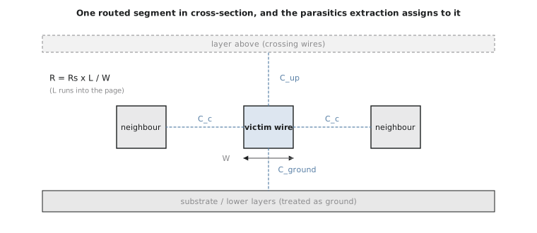
The output is a SPEF (Standard Parasitic Exchange Format) file with one entry per net, broken into as many resistor and capacitor elements as the route’s geometry needs. The next article reads one of these entries in detail.
A small RC calculation
To get a feel for the sizes involved, take one straight segment on met2. The resistance of a rectangular conductor is
$$R = R_s \times \frac{L}{W}$$
where $R_s$ is the layer’s sheet resistance in ohms per square and $L/W$ is the number of squares the segment spans. A wire twice as long as it is wide is two squares.
SKY130’s met1 and met2 are about 0.125 Ω per square (check the PDK documentation for the exact figure in your release). A segment 20 µm long and 0.14 µm wide is about 143 squares, so
$$R \approx 0.125 \times 143 \approx 18\ \Omega$$
For capacitance, a typical order of magnitude for a minimum-width wire with neighbours on both sides is 0.2 fF per micron of length, so this segment carries about 4 fF.
Now compare those numbers with the cell driving the wire. A small standard cell has an effective output resistance of a few kilo-ohms. Charging 4 fF through, say, 2 kΩ takes on the order of 8 ps. The wire’s own 18 Ω charging its own 4 fF contributes a fraction of a picosecond. So for the lengths inside a block like the UART, the dominant effect of a wire is the capacitance it hangs on its driver. Resistance becomes important on long routes, on minimum-width lower layers, and above all on the local interconnect layer li1, which is far more resistive than the metal layers.
That is why long nets such as parity_net tend to dominate a design’s slow paths once extraction replaces the estimates. More length means more capacitance for the driver to charge, and on a long enough route the resistance starts to add on top.
The numbers above are rough, chosen to show the shape of the calculation. Extraction does the same thing with the PDK’s real coefficients, for every segment of every net in the design.
Hands-on: find the extraction rules
Before running an extraction, confirm the rules file exists in your PDK installation. The OpenLane support files for SKY130 ship OpenRCX rules for three extraction corners:
ls $PDK_ROOT/sky130A/libs.tech/openlane/ | grep -i openrcx
You should see files named along the lines of rules.openrcx.sky130A.min.calibre, .nom. and .max., one per extraction corner (the exact names vary slightly between PDK releases). Open the nominal one and skim the first few dozen lines. You will see per-layer resistance and capacitance coefficients, the same kind of numbers used in the calculation above, only far more complete. We will come back to why there are three of them in Section 7.3.
One thing I would warn against is assuming that extraction only matters for long nets and can be approximated for short local ones. Two short wires running in parallel for a few microns at minimum spacing can couple more capacitance than a much longer, well-isolated wire picks up to ground. Extraction has to walk every net, not just the ones that look long in a layout viewer.
Practice Exercise
A segment on li1 is 8 µm long and 0.17 µm wide. Take li1’s sheet resistance as roughly 12.8 Ω per square. Estimate its resistance and compare it with the 20 µm met2 segment above. What does this suggest about how the router should use li1?
Solution
Squares = L/W = 8 / 0.17 ≈ 47. Resistance ≈ 12.8 × 47 ≈ 600 Ω.
That is more than thirty times the 18 Ω of the met2 segment, even though the li1 segment is less than half as long. Resistance depends on the number of squares and on the layer’s sheet resistance, not on length alone, and li1 is about a hundred times more resistive per square than met1 or met2. This is why SKY130 uses li1 mainly for short connections inside and between neighbouring cells, and why routers are configured to avoid long signal runs on it. A few hundred ohms in series with a large downstream load is enough to show up in a timing report.
In the next article we open a real SPEF file and go through each of its sections, using the net this module has been following.