Clock Net Routing
Picture an ordinary signal net running into congestion during detailed routing. TritonRoute rips it up, tries another track, maybe another layer, and reroutes it a few microns from where it originally planned. For almost every net that is a non-event. The net still connects the same two points by a slightly different path and nothing about its function changes. Try the same move on the clock net TritonCTS built in Module 5 and you do not get a slightly different path to the same result. You get a different clock tree, one whose delay to every flop is no longer the balanced structure CTS spent a whole stage constructing.
What makes the clock net different
Every other net carries information whose timing matters only in a “delay under some budget” sense. Get a tx_data bit to the shift register with margin to spare and it does not matter whether the margin is comfortable or barely enough. The clock net’s job is different in kind. It is not trying to deliver a signal quickly. It is trying to deliver a signal to dozens of flops at nearly the same time as each other, the skew idea from Module 5. TritonCTS did not just find paths for the clock. It inserted buffers and shaped the topology specifically to equalise delay across every leaf, often adding delay to shorter paths to match longer ones.
That balance lives in the tree’s exact structure: which buffer feeds which flops, and the wire length from each buffer to each child. If detailed routing rips up one branch and reroutes it to dodge local congestion, it changes that branch’s wire delay without touching any other, and because skew is a relative quantity between branches, it reintroduces exactly the problem CTS was built to remove. An ordinary net rerouted differently is functionally identical. A clock branch rerouted differently can be worse, invisibly, until the next timing report.
How routing protects the tree
Clock routing in this module is therefore not “route it like everything else and hope”. OpenROAD’s routing steps treat the clock’s already-built topology as something to preserve, not re-derive. The physical routing follows the structure CTS committed to rather than re-planning clock connectivity from scratch. In practice, clock nets are routed with tighter limits on how much detour is tolerated relative to the path CTS assumed, and typically on more predictable, less congested layers so the router has less reason to detour in the first place.
This is also why Module 5 had you check post-CTS timing before routing. Post-CTS skew and latency were computed on estimated, not yet physically routed, wire delay. Post-routing timing in Module 7 rechecks the tree against real extracted parasitics from the routed wires. The two should be close if clock routing preserved the tree, and a large mismatch is itself a diagnostic: clock routing was forced into unusual detours somewhere.
So the right response to congestion near clock buffers is not to let the router find a different path for the clock branch and move on. It is to address the congestion itself, usually a placement density matter and Section 6.5’s theme, rather than accept a clock reroute that quietly perturbs the skew balance you validated in Module 5.
Spotting the tree in a routed clock net
A representative excerpt of the routed clk net from the DEF, showing the branches feeding two CTS buffers:
- clk
  + USE CLOCK
  + ROUTED met3 ( 120000 150000 ) ( 120000 180000 )
    NEW    met2 ( 120000 180000 ) ( 95000 180000 )
    NEW    met2 ( 120000 180000 ) ( 145000 180000 )
    NEW    met2 ( 95000 180000 ) ( 95000 210000 )
    NEW    met2 ( 145000 180000 ) ( 145000 208000 )
;
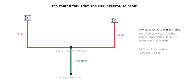
The trunk arrives on met3 from (120000, 150000) to (120000, 180000), then splits into two met2 branches, one heading left to x = 95000 and one right to x = 145000, the “one buffer feeding two children” fork from Module 5. The two branches then run up 30 um and 28 um respectively, 30000 and 28000 dbu, within 2 um of each other. That is not a coincidence. TritonCTS chose the buffer positions and branch topology to equalise delay to each side, and clock routing preserved that structure instead of re-optimising wirelength per branch. A signal router optimising purely for length would have no reason to produce two branches this close unless the destinations happened to be equidistant.
Practice Exercise
A congestion report shows a hotspot directly beneath one of the UART’s CTS buffers, and a nearby signal net is rerouted through a longer, more circuitous path to relieve it. The clock branch from that buffer is left untouched. Explain why leaving the clock branch alone was very likely the right call rather than an oversight.
Solution
Rerouting the signal net, whose exact path does not matter functionally, is the low-cost, low-risk fix. It resolves the hotspot without touching anything whose timing depends on balance. Rerouting the clock branch instead risks exactly the skew disruption this article describes: even a small detour on one branch shifts its delay relative to its siblings, undoing Module 5’s work in a way that might not surface until post-routing timing in Module 7. Leaving the clock alone and pushing the signal out of the way is the priority principle applied correctly.
You have reasoned through why power and clock nets are treated differently. The next article shows the difference with your own eyes: open the routed UART in KLayout and confirm that power and clock routing look structurally nothing like ordinary signal routing.