Power and Ground Routing
Section 6.4 is about the nets that get treated differently. Every signal net routed so far in this module, tx_data, rx_start_bit, baud_tick, was free to take whatever path global routing and TritonRoute found for it, on whatever layer made sense, at whatever width the rules required and no more. VPWR and VGND get none of that freedom, on purpose. They are not routed by the same process at all. They were built as a fixed, oversized skeleton of rings and straps back in Module 3, and by the time you reach this module, signal routing has to treat that skeleton as a given.
Why power cannot be routed like a signal
A signal net carries one logical value at a time and needs just enough width and path to meet its timing and DRC obligations. A power net has to deliver current continuously to every cell in the design at once, with as little voltage drop along the way as possible. Route VPWR like a signal, thin and wherever a router finds a convenient path, and every cell far from the source sees a meaningfully lower supply than cells near it. That is IR drop, which you met in Module 3. Enough of it and cells do not just slow down, they fail to switch.
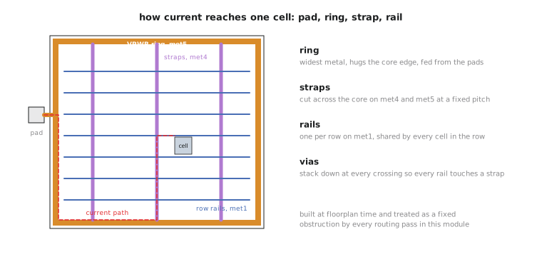
The fix is architectural. Power distribution is a deliberately over-provisioned, low-resistance network: rings around the core perimeter, connected to straps that cut across the design on the highest, lowest-resistance layers, sized so that current has several short paths to every cell rather than one long thin one.
Why it has to happen first
This is the part that surprises people coming from a “route everything and see” model. The power grid is not routed alongside signal nets and not after them. It is built during floorplanning, before placement runs, and by the time routing executes in this module its geometry is fixed, occupying real space on met4 and met5 that signal routing cannot use.
The ordering is required, not just conventional. Signal routing’s job is to find legal paths for every net given whatever already occupies the layers, and the grid, because of its size and its criticality, has to be one of those fixed givens. If power ran after or alongside signals, either the grid would be squeezed into whatever irregular space signal nets left, defeating the point of over-provisioning it, or signal routing would be renegotiating around a grid that kept changing shape underneath it. Fixing power first gives everything downstream a stable floor.
In OpenLane the grid is generated inside run_floorplan, driven by the FP_PDN_* fields such as FP_PDN_VWIDTH, FP_PDN_HWIDTH and FP_PDN_VPITCH you set in Module 3, and committed to the design database before placement, CTS or routing run. Global and detailed routing read it as an existing obstruction, the same way they read a macro.
A clean signal routing report does not mean the grid is fine. Power delivery is verified separately, by IR drop analysis in Module 8, because a grid can be perfectly legal as drawn geometry and still be electrically too thin in some region. Routing-clean and power-adequate are different claims, the same distinction as global-routing-clean and detailed-routing-clean.
Reading the grid in a DEF excerpt
A representative slice of the VPWR special net from the UART’s routed DEF:
- VPWR
  + USE POWER
  + ROUTED met5 1600 + SHAPE RING   ( 0 0 ) ( 303300 0 )
    NEW    met5 1600 + SHAPE RING   ( 0 303300 ) ( 303300 303300 )
    NEW    met4 800  + SHAPE STRIPE ( 40000 0 ) ( 40000 303300 )
    NEW    met4 800  + SHAPE STRIPE ( 150000 0 ) ( 150000 303300 )
    NEW    met4 800  + SHAPE STRIPE ( 260000 0 ) ( 260000 303300 )
;
Coordinates are database units across the 303.3 um square core, and the 1600 and 800 after each layer name are the wire widths. The SHAPE keyword labels each segment, but you can tell them apart from geometry alone, and it is worth being able to. The two met5 segments run along the bottom edge (y = 0 to y = 0, full width) and the top edge (y = 303300, full width). With the implied left and right edges they trace the core’s perimeter, which is what a ring does. The three met4 segments are each a full-height vertical run at a fixed x, cutting across the interior at intervals rather than following the perimeter, which is what straps do. Perimeter-tracing shapes on the widest top layer are rings; interior-crossing shapes at a regular pitch are straps.
Practice Exercise
A junior designer proposes routing a wide, high-current internal bus with the same ring-and-strap approach as power, since it also carries a lot of current. What actually determines whether a net needs power-style treatment, and does “carries a lot of current” qualify on its own?
Solution
The distinguishing factor is not current. It is that power and ground connect to every cell in the design at once and must hold a stable voltage everywhere, which is what demands a redundant, low-resistance, multiply connected grid rather than a single path. A high-current bus, however wide, connects a specific, limited set of sources and sinks. It can be sized with wider traces and extra vias using ordinary signal routing without the ring-and-strap architecture, because it does not have the “reach everything with minimal drop” requirement that defines power distribution. Universal connectivity qualifies a net; current alone does not.
Power and ground get special treatment because of what they connect to. The clock net gets it too, for a completely different reason: it has already been carefully balanced, and ordinary rerouting would undo that work.