Legal but Unroutable
Go back to Section 4.2 and look at what legalisation actually verifies: every cell sits on a real row at a real site, and no two cells overlap. That is the entire contract. Nowhere in it is there any statement about wires, because legalisation is a cell placement operation with no awareness of routing resources at all. It is entirely possible, common even on a badly tuned run, to have a design that is 100% legal by every legalisation check and 0% routable in one region, because the two checks test completely different things.
The mechanism
Picture a small region of the core where a wide multiplexer, an opcode decoder or a similar high-fanout structure got placed. The cells themselves fit fine, side by side, no overlaps, every one on a legal site. Legalisation has no complaint. But every one of those cells has pins that need wires, and a decode structure routinely needs far more net crossings through its local boundary than a typical region of the same size. If the nets needing to cross that boundary exceed the tracks actually available there, on the layers those nets need, you have a routing demand that legalisation was structurally incapable of noticing.
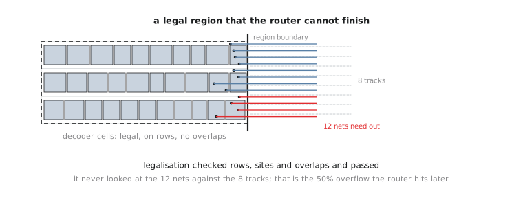
Downstream, this shows up in one of two ways once you reach Module 6. Either the router detours around the congestion using extra layers or longer paths, quietly making every timing path through that region worse than the placement-stage estimates suggested, or it cannot find a legal route for some nets at all and leaves unrouted nets or DRC spacing violations behind as it packs wires tighter than the rules allow.
Computing the overflow
alu8’s opcode decode region needs 40 nets to cross one GCell boundary on met2. That layer, at that boundary, has 32 tracks.
$$\text{Overflow} = \frac{\text{Demand} - \text{Capacity}}{\text{Capacity}} \times 100% = \frac{40 - 32}{32} \times 100% = 25%$$
The boundary is oversubscribed by 25%. Eight more nets need to cross than there is room for, on that layer, at that location. This is a legal, fully placed region of the design, every cell there passed legalisation cleanly, that is simultaneously guaranteed to cause routing trouble.
This exact scenario, a decode or mux structure with unexpectedly high local fanout, is one of the commonest sources of routing congestion in real designs. It is rarely obvious from the RTL. A case statement with a dozen branches looks unremarkable in Verilog and still synthesises into a structure whose physical fanout creates a real hotspot once placed. The mistake is waiting until routing actually fails before believing the problem is real. By the time detailed routing reports unrouted nets you have already spent the runtime for CTS and global routing on a design that congestion analysis, run here at placement, would have flagged for free.
Practice Exercise
A region needs 55 nets to cross a boundary where met1 has 60 tracks, and separately needs 28 nets to cross a boundary where met3 has 20 tracks. Compute the overflow for each and identify the actual routing risk.
Solution
met1: demand 55 is under capacity 60, so no overflow. (\frac{55-60}{60} \times 100% = -8.3%), a negative number meaning spare capacity.
met3: demand 28 exceeds capacity 20. (\frac{28-20}{20} \times 100% = 40%) overflow, a substantial oversubscription on this layer at this boundary.
The met3 boundary is the real risk. Worth internalising: congestion is always a per-layer, per-location question, never one design-wide number. A design can look fine in aggregate while one layer at one boundary is badly oversubscribed, and that is exactly the localised problem a summary statistic hides.
Understanding the failure mode is one thing. Generating and reading a congestion map for a real design is the practical skill. The next article runs OpenROAD’s own congestion estimate on alu8’s placement and interprets the real output.