What Pre-CTS Numbers Cannot Tell You
The previous article closed with one path passing at 1.65 ns of slack and another at 0.45 ns. Both got MET. It would be easy to read that and move straight on to CTS feeling good about alu8. Resist that. This article exists to name, explicitly and completely, everything still missing from the picture you just read.
The complete list
| What is still missing | Why it matters | Where it gets modelled |
|---|---|---|
| Real clock insertion delay and skew | Pre-CTS assumes every flop’s clock arrives at the same instant with zero delay. A real clock tree gives every flop a different insertion delay, and the difference between two flops’ delays (skew) adds to or subtracts from setup and hold margin directly. | Module 5 (Clock Tree Synthesis) |
| Real routed wire delay and parasitics | Pre-CTS wire delay comes from placement-geometry estimates, not from an actual routed shape with real vias, layer changes and coupling to neighbouring wires. | Module 6 (Routing) and Module 7 (Parasitic Extraction) |
| Crosstalk and signal integrity | Two adjacent switching wires can change each other’s delay. The concept does not exist until real routed geometry does. | Module 7 (Signoff Timing) |
| Multi-corner, multi-mode variation | A single pre-CTS run typically checks one process, voltage and temperature corner. Real signoff checks every corner the part must work in. | Module 7 (Signoff Timing) |
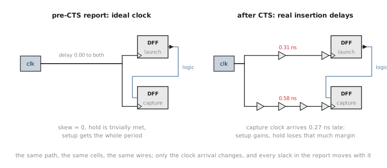
Why hold is the one to really worry about
Setup checks care about a path being fast enough relative to a full clock period. With 20 ns of budget on alu8 there is a lot of room to absorb added delay before setup breaks. Hold checks are different. They care about a path being slow enough that data does not race past the very next clock edge, and the margin involved is typically a fraction of a nanosecond, set by the receiving flop’s hold requirement and not by the period at all.
Under an ideal, zero-skew clock, hold is nearly always trivially met, because launching and capturing flops see the edge at the same instant and there is no skew eating into that thin margin. The moment Module 5 gives every flop a real insertion delay, the free pass disappears. Two flops far apart in the clock tree can easily end up with tens or a couple of hundred picoseconds of skew between them, and hold margin is exactly the size where a number like that flips a passing check into a violation that never existed, and could not have existed, in any report you have read so far.
This is why “the design passed setup and hold at placement” is not a claim an experienced physical design engineer puts any weight on. The honest version is “the design passed setup under an ideal clock, and hold was not meaningfully tested”. Real hold closure happens post-CTS, because you need a real clock tree before a hold violation is even a physically grounded thing to fix.
None of that makes pre-CTS numbers throwaway. A badly placed critical path, Section 4.1’s wirelength-against-timing conflict made real, already shows up here, and it is far cheaper to fix by adjusting placement now than to discover the same root cause five stages later buried under real skew and real parasitics. Pre-CTS timing is a checkpoint worth taking seriously precisely because it is incomplete. It is your one chance to catch a placement-level problem before the expensive stages compound it.
Judging the margin
Recall the two paths: 1.65 ns and 0.45 ns of pre-CTS setup slack. Once Module 5 builds it, alu8’s clock tree is expected to introduce roughly 0.2 to 0.6 ns of skew between arbitrary flop pairs. That is a reasonable ballpark for a design this small, not a prediction.
Which path would you flag as at real risk of failing setup once a clock tree exists, and which is comfortably safe?
The 0.45 ns path is the one to flag. If unfavourable skew in the 0.2 to 0.6 ns range lands on it, meaning the capture flop’s clock arrives earlier relative to the launch flop’s clock than the ideal assumption allowed, some or all of that thin margin simply evaporates and the path can go negative post-CTS. The 1.65 ns path has enough cushion that the same skew range is unlikely to consume it in any realistic case. This judgement, how much margin is actually safe margin, is what turns a raw slack number into something you act on rather than report.
Practice Exercise
A third path reports 0.15 ns of pre-CTS setup slack. Using the same 0.2 to 0.6 ns expected skew range, would you consider this path effectively failing in practical terms, even though the report prints MET?
Solution
Yes, in practical terms. 0.15 ns of margin sits entirely inside the range of skew the eventual clock tree is expected to introduce, so even a mild unfavourable outcome is enough to flip this path negative once CTS runs. A path this close to zero should not be treated as passing and done because the report currently says MET. Treat it as a likely post-CTS violation: watch it closely, or address it now if there is an obvious placement-level fix, such as shortening the distance between the two flops, while it is still cheap.
Every one of these gaps traces back to one missing piece: nothing has confirmed where the wires can actually go yet. Section 4.4 addresses that directly with congestion analysis, and the specific failure where a placement is perfectly legal and the routing simply will not fit.