Project 4, Part 1: Setup and Floorplan
Every design in this module so far has been small enough that floorplanning was nearly a formality. This one is not. The cpu_top processor from the Verilog course’s Module 10, with its instruction and data memories, four-register file, ALU and control state machine, is several times larger than the UART, and that is the size at which utilisation and aspect ratio stop being background details and start deciding whether the rest of the project goes smoothly.
The design
cpu_top brings together the pieces of that capstone: an 8-bit datapath, a multi-cycle control state machine, a 4-entry register file, and two memories, imem and dmem, built from flops rather than a hard macro. In the Verilog course both memories were 256 bytes deep. As flops, that would be 2 × 256 × 8 = 4,096 flip-flops for memory alone, which is exactly the job a hard macro like Project 3’s exists for. For this project I have set both memories’ DEPTH parameter to 32 bytes, which keeps the design honest to synthesise from flops and leaves Project 3 as the only macro project.
openlane --flow Classic --run-tag cpu_run1 --to Yosys.Synthesis designs/cpu_top/config.json
=== cpu_top ===

   Number of cells:               1842
     sky130_fd_sc_hd__dfxtp_1       612
     sky130_fd_sc_hd__mux4_2        180
     sky130_fd_sc_hd__nand2_1       244
     sky130_fd_sc_hd__a221oi_1       96
     ...

   Chip area for module '\cpu_top': 22380.6
1,842 cells, about four times the UART, and 612 flops: 512 in the two memories, the rest in the registers, program counter, instruction register and state machine. The memories’ read muxes account for most of the mux4 cells. At this size some problems, congestion and real timing pressure at the slow corner, finally show up.
The utilisation decision
Module 3 introduced utilisation as a trade-off between die area and routability. Here we pick a real number:
$$ \text{Core area} = \frac{\text{Cell area}}{\text{Target utilisation}} $$
At a conservative 40%:
$$ \text{Core area} \approx \frac{22{,}381}{0.40} \approx 55{,}950\ \mu m^2 \quad (\text{about } 237 \times 237\ \mu m) $$
This project deliberately picks a tighter 55%, leaving placement and routing less room than in any earlier project:
$$ \text{Core area} \approx \frac{22{,}381}{0.55} \approx 40{,}690\ \mu m^2 \quad (\text{about } 202 \times 202\ \mu m) $$
{
    "DESIGN_NAME": "cpu_top",
    "VERILOG_FILES": "dir::src/cpu_top.v",
    "CLOCK_PORT": "clk",
    "CLOCK_PERIOD": 12,
    "FP_SIZING": "relative",
    "FP_CORE_UTIL": 55,
    "FP_ASPECT_RATIO": 1,
    "PL_TARGET_DENSITY": 0.62,
    "PL_ROUTABILITY_DRIVEN": false,
    "FP_PDN_VPITCH": 50,
    "FP_PDN_HPITCH": 50
}
PL_ROUTABILITY_DRIVEN is switched off here to make the placement run faster, something people do on small designs. We will see in the next article that it was not a good idea on this one.
A mistake to avoid is treating utilisation as a number to push up for area alone, without looking at the design. A control-heavy netlist with wide multiplexers, like this one, has many irregular, high-fanin nets compared with a regular datapath of the same size, and pushing its utilisation up is a common way for real projects to create their own routing congestion late in the flow.
Aspect ratio
FP_ASPECT_RATIO: 1 keeps the core square. As Module 3 explained, a square minimises average wirelength for a design with no strong direction in its connectivity, and cpu_top’s control unit talks to every other block in every direction. A stretched core would help only if the connections had a clear long axis, like a pipeline, and they do not.
Power planning
OpenLane’s default strap pitch for SKY130 is around 150 µm. On a core only 202 µm across, that would give just one vertical and one horizontal strap, leaving cells on the far side of the core a long way from any strap, fed only through the thin met1 rails. So the config reduces the pitch to 50 µm in both directions, which gives four straps each way, as in Figure 1, and keeps the default strap width.
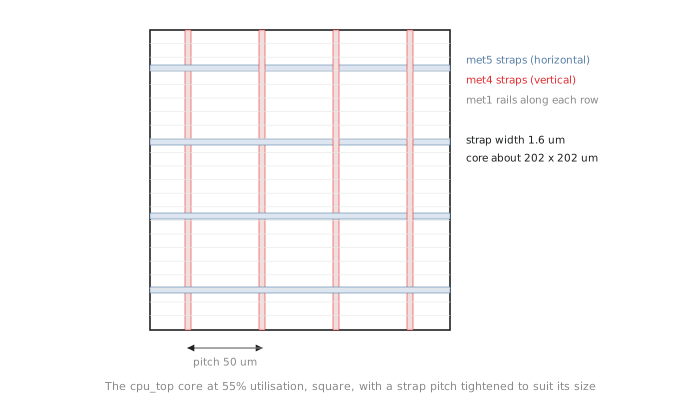
With 612 flops switching on the same clock edge, this design draws more current than anything earlier in the module, and the IR drop reasoning of Module 3 says the levers are always the same: closer straps, wider straps, or both. Here the pitch was the one that mattered.
openlane --flow Classic --run-tag cpu_run1 --from OpenROAD.Floorplan --to OpenROAD.GeneratePDN \
         designs/cpu_top/config.json
Core area: 201.710 x 201.620 um
Number of rows: 74
74 rows. A quick static IR drop estimate on the new grid, with the placement-stage power figures, gives a worst drop of about 6 mV. That is far inside the budget, but this is the first project where the number is worth checking rather than assuming.
Every decision in this article is one that Projects 1 to 3 also made, only in their easy form. Utilisation was 35 to 45% and uneventful; here it is 55% and chosen to create pressure. The aspect ratio was square by default; here it is square for a reason about connectivity. The strap pitch was the default; here it was changed because the default does not suit this core. Nothing new in concept, all new in consequence.
Practice Exercise
If FP_ASPECT_RATIO were 2 instead of 1 for this design, a core twice as tall as it is wide, which floorplan numbers would change, and which later stage would most likely have new difficulty?
Solution
The core area would stay about the same, about 40,700 µm², since it depends only on cell area and utilisation, but the core would become roughly 143 µm wide and 285 µm tall. There would be more rows, each shorter.
For a design whose control unit connects to everything, a long, thin core increases average wirelength, because more nets have to cross the long dimension. Placement would feel it first, with a harder wirelength problem, and routing next, with more demand along the long axis and congestion likely to build up across the middle of the core. That is the self-inflicted difficulty Module 3 warns about when the aspect ratio is chosen without a connectivity reason.
Synthesis, utilisation and the power grid are set for a design bigger than anything else in the module. In the next article we run placement, CTS, routing and signoff timing, and this time it does not go cleanly: one congestion problem and one slow-corner setup violation, both real and both fixed on the page.