Project 3, Part 1: Integrating a Hardened Macro
Every design so far in this module was built entirely from standard cells, synthesised the same way and placed by the same tool. That stops here. This project is a small controller around a hardened SRAM macro: a block of memory that was generated and verified once, and is handed to every design that uses it as a sealed object. You will never synthesise it, place anything inside it or route through it. Your job is all about its boundary.
The macro
The memory is one of the OpenRAM-generated SRAM macros made for SKY130, sky130_sram_2kbyte_1rw1r_32x512_8: 2 KB organised as 512 words of 32 bits, with one read/write port (port 0) and one read-only port (port 1). What it gives you is not RTL but a set of fixed views:
| View | Used for |
|---|---|
| LEF | Floorplanning, placement and routing: the outline, the pins and the obstructions |
| GDS | The real layout, merged into the final GDS at streamout |
Liberty (.lib) |
STA: the macro’s timing at its pins, as a black box |
| Verilog blackbox | Synthesis: the module’s port list, with no contents |
Yosys never sees inside the macro. The controller instantiates it as a module with the right ports, and the flow treats that instance as a fixed, pre-built block.
module sram_ctrl (
    input         clk, rst_n,
    input  [8:0]  addr,
    input  [31:0] wdata,
    input         we, re,
    output [31:0] rdata,
    output        ready
);
    wire csb0 = ~(we | re);   // chip select, active low
    wire web0 = ~we;          // write enable, active low

    sky130_sram_2kbyte_1rw1r_32x512_8 u_sram (
        .clk0(clk), .csb0(csb0), .web0(web0), .wmask0(4'hF),
        .addr0(addr), .din0(wdata), .dout0(rdata),
        .clk1(clk), .csb1(1'b1), .addr1(9'd0), .dout1()   // port 1 unused
    );
    // ready/handshake logic omitted: a thin synchronous wrapper
endmodule
The control signals are active low, which is OpenRAM’s convention, and the unused read port is disabled by holding its chip select high.
Declaring the macro in the config
{
    "DESIGN_NAME": "sram_ctrl",
    "VERILOG_FILES": "dir::src/sram_ctrl.v",
    "VERILOG_FILES_BLACKBOX": "dir::macro/sky130_sram_2kbyte_1rw1r_32x512_8.v",
    "EXTRA_LEFS": "dir::macro/sky130_sram_2kbyte_1rw1r_32x512_8.lef",
    "EXTRA_GDS_FILES": "dir::macro/sky130_sram_2kbyte_1rw1r_32x512_8.gds",
    "EXTRA_LIBS": "dir::macro/sky130_sram_2kbyte_1rw1r_32x512_8_TT_1p8V_25C.lib",
    "MACRO_PLACEMENT_CFG": "dir::macro_placement.cfg",
    "PL_MACRO_HALO": "10 10",
    "FP_PDN_MACRO_HOOKS": "u_sram vccd1 vssd1 vccd1 vssd1",
    "CLOCK_PORT": "clk",
    "CLOCK_PERIOD": 20,
    "FP_SIZING": "absolute",
    "DIE_AREA": "0 0 1000 700"
}
The EXTRA_* entries are not new ideas. They are the standard cell views from Module 2.3, LEF for shape and Liberty for timing, supplied by hand for one block instead of coming with the PDK’s library. Newer OpenLane 2 releases collect all of a macro’s views and its placement under a single MACROS entry; the information is the same. The die size is absolute this time because the macro alone is several hundred microns across, far larger than all the controller logic, and a size worked out from the standard cell area would make no sense.
MACRO_PLACEMENT_CFG, PL_MACRO_HALO and FP_PDN_MACRO_HOOKS are the decisions this project is about.
Placing the macro
# macro_placement.cfg: instance name, x, y, orientation
u_sram 180 60 N
That line fixes the lower-left corner of the instance u_sram at (180, 60) µm, unrotated. Three decisions from Module 3.4 go into it, shown in Figure 1:
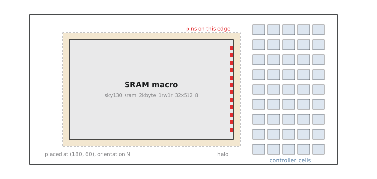
- Orientation. The macro’s pins are fixed in its LEF, and in this floorplan the address, data and control pins face the right-hand side of the macro. Orientation decides which way that edge faces. Pointing it at the controller logic keeps those nets short; pointing it at the die edge would force every one of them to route around the whole macro.
- Halo.
PL_MACRO_HALOkeeps standard cells 10 µm away from the macro on every side. That leaves room for the power connections to the macro and for routing to reach its pins without cells packed against its edge. Too small a halo causes routing trouble right at the boundary; too large simply wastes area. - Blockages and power. The macro’s own area is automatically blocked for standard cells, and its internal metal is an obstruction to the router. The SRAM brings its own power ring and pins (
vccd1,vssd1), andFP_PDN_MACRO_HOOKStells the power grid generator to connect the design’s supply nets to those pins, instead of leaving the macro unpowered or running straps straight over it.
The mistake I would warn against is setting the halo to zero, reasoning that the macro’s outline is already a blockage. With no halo, cells can be placed hard against the macro, leaving no room for the power connections or the pin access routing. The problem then appears much later, as routing violations or an unconnected macro supply, instead of at placement.
Running the floorplan
openlane --flow Classic --run-tag sram_run1 --to OpenROAD.Floorplan designs/sram_ctrl/config.json
In the log and in the floorplan DEF you should see the macro placed and fixed at (180, 60) in orientation N, and standard cell rows created around it, not across it. Open the floorplan in the OpenROAD GUI or KLayout and check that the macro sits where you intended, with its pin edge facing the empty area where the controller logic will go. This is the blockage behaviour Module 3 described in the abstract, now on a real macro.
Practice Exercise
If the orientation were changed from N to FN (mirrored left to right) without changing the placement coordinate, what is the first thing you would check before trusting the floorplan, and why?
Solution
Check where the macro’s pins now are relative to the controller logic. Mirroring moves the pin edge to the opposite side of the macro without changing its bounding box coordinates, because the pin positions in the LEF are defined relative to the macro’s own origin. The pin edge would now face the left of the die, away from the space where the controller cells will be placed, and every signal to the macro would have to route around it.
A floorplan can be perfectly legal, with no overlaps and every rule met, and still be poor: legality says nothing about whether the pins are easy to reach. That is the routing question the next article looks at.
The macro is fixed in place, with its halo and power connections, and the rows go around it. In the next article we place the controller cells in the remaining space, route the design, and see how routing near a macro behaves differently from the open areas of Projects 1 and 2.