Project 2, Part 2: CTS and Timing Closure
In the previous article we set up the UART and saw that synthesis and floorplanning were easy. In this article we get to the part that is not. Placement is uneventful on a design this size, but as soon as a real clock tree replaces the ideal clock, a hold problem appears that did not exist before CTS. This is the single most reliable surprise for new physical designers, which is why Module 5 spent a whole article on it.
Placement
openlane --flow Classic --run-tag uart_run1 --from OpenROAD.GlobalPlacement --to OpenROAD.DetailedPlacement \
         designs/uart/config.json
[INFO DPL-0001] Placed 431 instances
Max displacement: 1.4 um
Clean, as expected. This is not where the project’s difficulty lies.
Clock tree synthesis
openlane --flow Classic --run-tag uart_run1 --from OpenROAD.CTS --to OpenROAD.CTS designs/uart/config.json
From the CTS log and the clock skew report that follows it:
[INFO CTS-0010] Clock net "clk" has 62 sinks.
[INFO CTS-0018] Created 9 clock buffers.
Max skew: 0.142 ns
Max latency: 0.486 ns
62 sinks, one per flop, matching the 62 dfxtp cells from synthesis. That is always worth confirming, because a mismatch means some flop is not on the tree. 142 ps of skew is tiny against a 10 ns period, but “small compared with the setup budget” and “small compared with a hold requirement” are very different statements.
The hold violation
Open the post-CTS design in OpenROAD with the libraries and the SDC, and ask for the worst hold paths:
% read_db runs/uart_run1/<cts step>/uart_top.odb
% read_liberty $PDK_ROOT/sky130A/libs.ref/sky130_fd_sc_hd/lib/sky130_fd_sc_hd__tt_025C_1v80.lib
% read_sdc designs/uart/uart_top.sdc
% set_propagated_clock [all_clocks]
% estimate_parasitics -placement
% report_checks -path_delay min -group_path_count 2
Two of the paths it reports, simplified:
Startpoint: rx_bit_counter_reg[2]    Endpoint: rx_bit_counter_reg[3]    Path Type: min

  0.312   clock latency at rx_bit_counter_reg[2]
  0.089   clock to Q
  0.041   combinational (one inverter, short net)
  0.442   data arrival time

  0.397   clock latency at rx_bit_counter_reg[3]
  0.036   library hold time
  0.433   data required time

  slack  +0.009 (MET)

Startpoint: baud_counter_reg[5]      Endpoint: baud_counter_reg[6]      Path Type: min

  0.298   clock latency at baud_counter_reg[5]
  0.089   clock to Q
  0.018   combinational (one fast gate, very short net)
  0.405   data arrival time

  0.401   clock latency at baud_counter_reg[6]
  0.036   library hold time
  0.437   data required time

  slack  -0.032 (VIOLATED)
There it is: a real hold violation on the baud counter, bit 5 to bit 6, 32 ps short. Figure 1 shows it as waveforms.
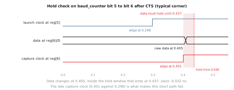
Compare the two paths. The receiver’s bit counter passes, only just, with 9 ps. The baud counter path has almost no logic between the two flops, just 18 ps, and the flops sit next to each other after placement. On its own that would be fine. What breaks it is the clock: the capturing flop’s clock arrives 103 ps later than the launching flop’s (0.401 against 0.298). CTS kept the skew across the whole tree to 142 ps, but it does not make every pair of sinks equal, and this pair happens to have the capture late and the data path short.
This is the exact shape Module 5 described: hold violations appear on short paths between nearby flops, and only after CTS puts real, unequal delays into the clock network. The ideal-clock STA in the previous article could never have shown it.
Fixing it
The standard fix is to add delay in the data path, not in the clock, so that this endpoint’s data changes later without disturbing the balance of the rest of the tree. The resizer does this for you:
% repair_timing -hold -hold_margin 0.05
[INFO RSZ-0046] Found 1 endpoints with hold violations.
[INFO RSZ-0032] Inserted 1 hold buffers.
It inserted one small buffer, a sky130_fd_sc_hd__buf_1, on the net into baud_counter_reg[6]/D. Checking that endpoint again:
  0.405 + 0.086 = 0.491   data arrival time (the buffer adds 86 ps)
  0.437                   data required time

  slack  +0.054 (MET)
The -hold_margin 0.05 asked for at least 50 ps of hold slack, not just zero, and the resizer chose the smallest buffer that gives it. It is a deliberately small, local fix, the scale of intervention Module 5 recommends, instead of rebuilding the clock tree with a tighter skew target, which would change every sink’s timing.
In the real flow this is exactly what the post-CTS timing repair step would have done automatically. Now switch it back on (remove the RUN_POST_CTS_RESIZER_TIMING line) and let the flow continue with the fix in place.
Routing and multi-corner timing
openlane --flow Classic --run-tag uart_run1 --from OpenROAD.GlobalRouting designs/uart/config.json
Routing finishes with 0 violations, and the flow’s multi-corner STA on the extracted parasitics reports:
| Corner | Worst setup slack | Worst hold slack |
|---|---|---|
tt_025C_1v80 |
+2.94 ns | +0.08 ns |
ss_100C_1v60 |
+1.02 ns | +0.14 ns |
ff_n40C_1v95 |
+3.61 ns | +0.05 ns |
All positive. Notice where each extreme is. Setup is tightest at the slow corner, where cells are slowest and data only just makes the 10 ns period. Hold is tightest at the fast corner, where data races through fastest, and the 50 ps margin we asked for is exactly what is left there. This is Module 7’s point about checking every corner, seen on a real design.
Practice Exercise
The fast corner has the least hold margin, +0.05 ns. If a second hold violation appeared only at the fast corner, would adding a data-path buffer still be the right fix, or would the corner change your approach?
Solution
A data-path buffer is still the right fix, but its size has to be judged across corners. A buffer that adds just enough delay at the fast corner adds more delay at the slow corner, where the same cell is slower, and that extra delay comes out of the setup margin on the same path. On a path with plenty of setup slack that does not matter; on a tight one it can. So after any hold fix you re-run every corner, not only the one that showed the problem. The resizer’s repair_timing -hold already looks at all loaded corners and refuses fixes that would break setup, which is one reason to let it do the work, but the final multi-corner check is still yours.
We found a hold violation, understood it, fixed it with one small buffer and confirmed it at all three corners. In the next article we run the physical verification checks on the UART and name exactly what a combinational design like Project 1 could never have shown us.