Reading a Pre-Placement Timing Report
The last article of Section 2.4 showed a full OpenSTA report and used it to argue that synthesis-stage timing is optimistic. This article returns to the same report with a narrower goal: reading it well enough to reconstruct the slack by hand from the path segments, without the tool telling you the answer at the bottom.
The report, read slowly
Startpoint: b[7] (input port clocked by clk)
Endpoint:   _068_ (result_reg[6], rising edge-triggered flip-flop clocked by clk)
Path Group: clk
Path Type:  max

  Fanout  Cap     Slew    Delay   Time   Description
--------------------------------------------------------------------
                                   0.00   clock clk (rise edge)
                                   0.00   input external delay
                          2.00     2.00   input delay set_input_delay
     4    0.012   0.09    0.18     2.18   sky130_fd_sc_hd__xor2_1 (b[7] -> X)
     2    0.008   0.07    0.14     2.32   sky130_fd_sc_hd__mux2_1 (A0 -> X)
     3    0.010   0.08    0.21     2.53   sky130_fd_sc_hd__o21ai_1 (A -> Y)
     2    0.009   0.06    0.17     2.70   sky130_fd_sc_hd__mux2_1 (A1 -> X)
     1    0.004   0.05    0.09     2.79   sky130_fd_sc_hd__dfxtp_1 (D setup)
                                   2.79   data arrival time

                                  10.00   clock clk (rise edge)
                                   0.00   clock network delay (ideal)
                                  -0.08   library setup time
                                   9.92   data required time
--------------------------------------------------------------------
                                   9.92   data required time
                                  -2.79   data arrival time
--------------------------------------------------------------------
                                   7.13   slack (MET)
Startpoint and endpoint. Every path has two ends. b[7] is where the data originates, an input port constrained by the set_input_delay from Section 2.4. _068_ (result_reg[6]) is where it is captured, the D input of a flip-flop in the result register. Path Type: max means a setup check: does the data arrive early enough before the capturing edge? (A min path type is the hold check, the other half of the pair from the Verilog course’s timing module.)
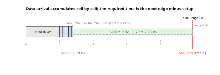
The Delay column, row by row. Each row after the input delay is the data passing through one more cell on its way from b[7] to the flop’s D input: xor2_1, mux2_1, o21ai_1, another mux2_1, then the flop’s own internal setup path. The Time column is cumulative: each row’s Time is the previous Time plus this row’s Delay. Confirm it: $2.00 + 0.18 = 2.18$, $2.18 + 0.14 = 2.32$, and so on to $2.79$ ns, the data arrival time.
Data required time. Working from the clock: the next active edge is at 10.00 ns. With an ideal clock network (previous article) that edge reaches the capturing flop’s clock pin at 10.00. Subtract the flop’s library setup time, how long before the edge D must be stable, a small number from the flip-flop’s Liberty entry, here 0.08 ns, and you get the required time, $10.00 - 0.08 = 9.92$ ns, the latest instant the data is allowed to arrive.
Slack. The whole report reduces to one subtraction:
$$ \text{slack} = t_{required} - t_{arrival} = 9.92 - 2.79 = 7.13\ \text{ns} $$
Positive slack means the path meets timing, with that much margin. Figure 1 draws the same arithmetic as a bar.
This is the setup relationship from the Verilog course’s timing module with real Liberty-derived delays in place of abstract variables. Do not read only the final “slack (MET)” line and skip the breakdown. The bottom line says whether a path is fine; the rows say why, and which cells contribute the most delay, which you will need constantly from Module 7 on, when fixing a violation means knowing which segment of a failing path to attack.
Practice Exercise
Another path in the same netlist reports a data arrival time of 8.65 ns against the same 9.92 ns required time. Compute the slack and say whether the path meets timing.
Solution
$$ \text{slack} = 9.92 - 8.65 = 1.27\ \text{ns} $$
Positive, so the path meets timing, but with far less margin than the +7.13 ns path above. This is the kind of path to watch once real wire delay and clock skew are added in later modules. A path with 7 ns of margin has a lot of room to absorb physical delay; a path with 1.27 ns has much less and is a realistic candidate to become a violation once the effects from Modules 4 to 7 are added.
You can now read both halves of a synthesis report, the structural half (stat) and the timing half (OpenSTA). In the next article, the last of the module, we turn both into a checklist: the numbers worth flagging as red flags before spending floorplanning effort on a netlist that might be broken.