Drive Strength and Cell Variants
The previous two articles covered the two views of one cell. This one is about why one logical cell comes in several physical sizes.
Grep a SKY130 library for buf_ and you will not find one buffer. You find sky130_fd_sc_hd__buf_1, buf_2, buf_4, buf_6, buf_8, buf_12, buf_16. The same function every time, Y = A. Why does a PDK ship seven distinct cells that all compute the same nothing?
Drive strength is about current, not logic
A cell’s drive strength is how much output current it can source and sink, which translates directly into how quickly it charges or discharges the capacitance on its output net. Physically, a higher-drive variant of the same logical cell uses wider transistors: more channel width means more current for the same gate voltage, at the cost of a larger footprint (a bigger LEF SIZE) and higher input capacitance (a bigger load on whatever drives it).
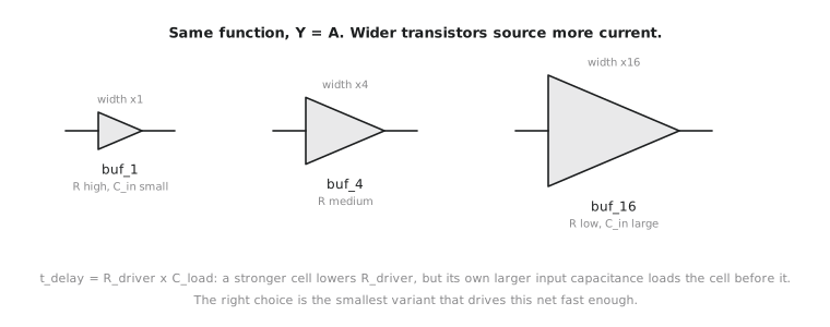
A gate’s delay, recall from the Liberty article, depends on the load it drives. A weak cell driving a heavy load is slow, not because the logic is complicated but because it takes longer to push enough current through narrow transistors to charge a large capacitance to a valid level. A strong cell driving the same load charges it faster by having more current available.
$$ t_{delay} \approx R_{driver} \cdot C_{load} $$
This is the RC intuition that appears constantly in physical design: reduce $R_{driver}$ (a stronger cell) or reduce $C_{load}$ (shorter wires, less fanout) and delay drops. Drive-strength variants give synthesis and later optimisation a lever on the $R_{driver}$ side, cell by cell, where it is needed and nowhere else.
Why not always use the strongest variant?
Because a buf_16 everywhere would be a strictly worse library to synthesize from. Its higher input capacitance loads its own driver more heavily (capacitance is contagious: every input pin’s capacitance becomes part of the load on whatever drives it), and its larger footprint costs area for no benefit on the many nets that only drive one small nearby gate. The goal is the smallest drive strength that comfortably meets timing on a given net, which is the per-net, load-aware decision that SYNTH_STRATEGY and the sizing and buffering optimisation in Module 7 automate. This is also the concrete mechanism behind Section 2.2: a DELAY strategy is not doing anything mysterious. A large part of what it does is prefer higher-drive variants on timing-critical nets, at the area cost just explained.
Pick a variant from a real fanout
A net in alu8 fans out from one gate’s output to four downstream inputs. Each presents roughly 0.003 pF, so the total load is about:
$$ C_{load} \approx 4 \times 0.003\ \text{pF} = 0.012\ \text{pF} $$
You are choosing between two variants (illustrative Liberty-derived numbers):
| Cell | Input capacitance | Max recommended load (illustrative) | Relative area |
|---|---|---|---|
sky130_fd_sc_hd__buf_1 |
0.00394 pF | ~0.008 pF | 1x |
sky130_fd_sc_hd__buf_4 |
0.00512 pF | ~0.020 pF | 2.4x |
The load on this net (0.012 pF) exceeds buf_1’s recommended maximum (0.008 pF). Driving it with buf_1 would produce a slower edge than necessary, hurting delay and signal quality on all four inputs. buf_4’s ceiling (0.020 pF) covers the 0.012 pF load with margin, at 2.4 times the area. For this net buf_4 is right, not because bigger is generally better but because this fanout needs the drive.
Pick by capacitance, not by fanout count. A net fanning out to four tiny inputs may need less drive than a net driving one input on a physically large, high-capacitance cell. Count is a rough proxy; capacitance is the real quantity.
Practice Exercise
Another net drives one downstream gate presenting 0.006 pF. Using the same table, which cell is the area-efficient correct choice, and why would the other one be wasteful rather than merely safe?
Solution
buf_1 is the correct, area-efficient choice: its recommended maximum (~0.008 pF) covers the 0.006 pF load, at less than half the area of buf_4. Choosing buf_4 would not be extra safety margin. It would add unnecessary input capacitance onto whatever drives this buffer (worsening that upstream gate’s delay, per the RC relation) and consume about 2.4 times the area for a net that never needed the current. Oversizing has a real cost; it is not a free hedge.
Section 2.3 covered what synthesis reads to make its cell choices. In the next article, Section 2.4 turns to the other input synthesis needs before any of those choices are meaningful: the timing constraints you, the designer, write.