create_clock and I/O Delay Budgets
The previous article’s create_clock -name clk -period 10.0 [get_ports clk] assumed a 50 percent duty cycle without saying so. That default is fine for most digital logic, but it is worth knowing what it defaults to, and why the input and output delays are not padding you add to be safe. Both model something specific.
Period versus duty cycle
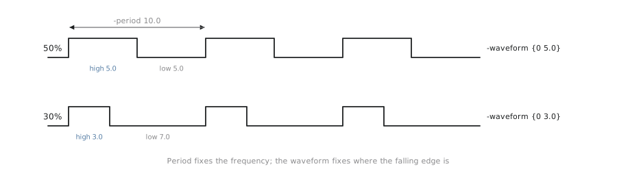
A clock’s period is how long one cycle takes. Its duty cycle is the fraction of that period the clock is high. create_clock -period 10.0 with no other argument implies a symmetric 50 percent duty cycle, high for 5.0 ns and low for 5.0 ns. Explicitly:
create_clock -name clk -period 10.0 -waveform {0 5.0} [get_ports clk]
-waveform {0 5.0} says the clock rises at time 0 within the period and falls at 5.0, half of 10.0. An asymmetric duty cycle:
create_clock -name clk -period 10.0 -waveform {0 3.0} [get_ports clk]
Here the clock is high for 3.0 ns of 10.0, a 30 percent duty cycle. Some real interfaces (certain DDR-style or source-synchronous protocols) use an asymmetric duty cycle because logic on different phases needs different settling time. For a block like alu8, 50 percent is the right and unremarkable choice, but knowing how to override it means you are not stuck when a design needs to.
I/O delays model the world outside the boundary
set_input_delay and set_output_delay are not safety margins. They are a statement about how this block connects to everything around it.
set_input_delay -clock clk 2.0 [get_ports {a[*]}]says: relative toclk’s active edge,adoes not arrive atalu8’s boundary instantly. Some upstream logic, a driving flip-flop plus whatever combinational logic sits between it andalu8, already consumes 2.0 ns beforeais valid at this block’s door.set_output_delay -clock clk 1.5 [get_ports {result[*]}]says: whatever is downstream ofresult, presumably another register on the same clock, needs 1.5 ns betweenresultbecoming valid and the next edge, for its own setup time and any logic in between.
Without these, synthesis assumes inputs arrive at the clock edge and outputs may settle at the next one, an unrealistically generous assumption. The next article and the timing-report articles in Section 2.5 come back to how misleading that generosity is.
How much time does alu8’s logic actually get?
With a 10.0 ns period, a 2.0 ns input delay on a, and a 1.5 ns output delay on result, the part of the period available to alu8’s own combinational path in the input-to-register direction is:
$$ T_{available} = T_{period} - t_{input_delay} - t_{setup} $$
where $t_{setup}$ is the capturing flip-flop’s setup time, a small Liberty-derived number, typically well under a nanosecond, that Section 2.5 shows in a real report. Roughly:
$$ T_{available} \approx 10.0 - 2.0 - 0.08 \approx 7.92\ \text{ns} $$
That 7.92 ns, not the full 10.0 ns period, is the real budget for alu8’s input-side logic. It is why Section 2.2’s comparison reported worst slack well under 10.0 ns even on a comfortably passing run. The constraint file, not the raw period, defines the target.
This is the mechanism behind a claim in the previous article: adding realistic I/O delays to a loosely constrained design can turn a passing report into a failing one with no RTL change. The logic did not get slower; the tool was told the truth about how much time it has. Setting an input or output delay to a comfortable round number like 0 ns “to be safe” claims signals arrive instantly, the most generous and least realistic assumption, and produces exactly the false-clean report both articles warn about.
Practice Exercise
alu8 will be integrated where op arrives late, 4.5 ns after the clock edge, because of a slow priority encoder feeding it, while a and b still arrive at 2.0 ns. With the 10.0 ns period, write the set_input_delay lines for all three inputs, and say which input constrains alu8’s logic hardest.
Solution
set_input_delay -clock clk 2.0 [get_ports {a[*]}]
set_input_delay -clock clk 2.0 [get_ports {b[*]}]
set_input_delay -clock clk 4.5 [get_ports {op[*]}]
op constrains the logic hardest. With only $10.0 - 4.5 = 5.5$ ns of the period left before even accounting for setup time, any path starting at op (which feeds the case-statement mux selecting the operation) has far less time than paths from a or b, which have roughly 8.0 ns. A path this constrained is exactly what a synthesis-stage timing report flags as the worst, least-slack path, which the next article examines.
Every timing number this module has quoted, including the 5.75 ns and 7.42 ns slack values from Section 2.2, came from a synthesis-stage STA run. In the next article we look at why those numbers, however clean, are still optimistic, and list what is missing from them.