From a Waveform to a Fix
The testbench says FAIL. The waveform shows something odd. The RTL looks fine. This is where most of the work in hardware happens, and it is methodical rather than dramatic. Here is a sequence that keeps you from spending hours on symptoms while the cause sits two signals upstream (Figure 1).
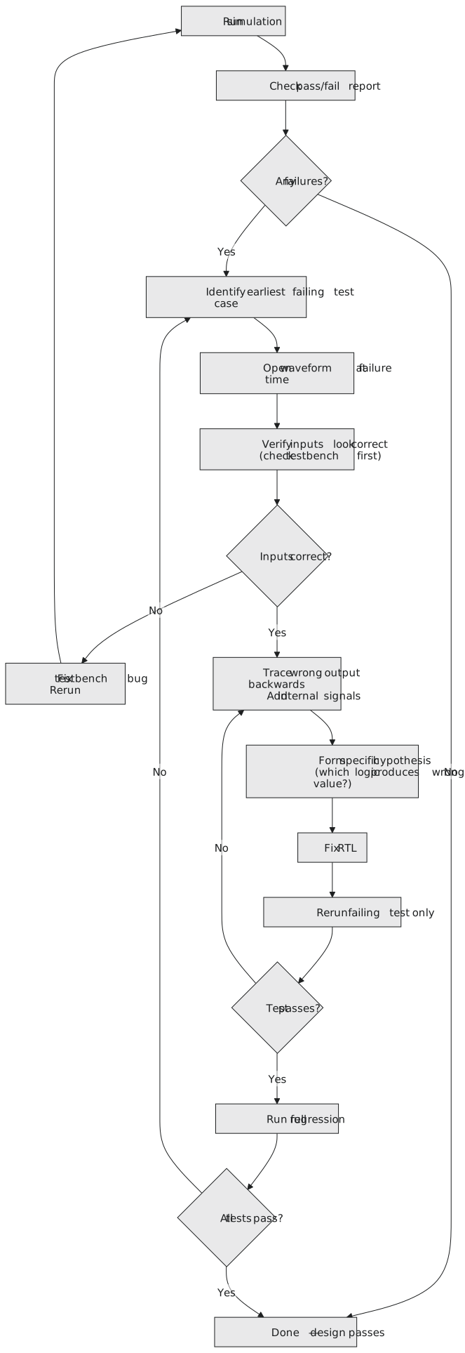
Two of the steps get skipped under pressure: checking the inputs, and running the full regression afterwards. Skipping the first wastes time on a design that was never broken. Skipping the second breaks something else while fixing this.
Use the message
A good $error does half the work:
ERROR at 170 ns: count expected 15, got 0
Which signal, what was expected, what came out, and when. Go to 170 ns in the waveform. You are not searching; you have been told where to look. This is why the thirty seconds spent on a message in section 6.4 are worth it.
Check the inputs
Before blaming the design, confirm what it was given. At 170 ns, is reset released? Is the clock running, and is this the cycle you think it is? Did the stimulus do what you meant? Testbench bugs are common: an off-by-one in the stimulus, a reset never released, an input driven on the edge. If the inputs are wrong, fix the testbench and re-run before touching the RTL. The waveform shows what the design received, which is not always what you intended to send.
Trace back
With the inputs right, add the signals that feed the wrong output, a level at a time, until you find the first one that is wrong. For a counter that is the incremented value and the wrap comparison. Does the count reach 14 and jump to 0, with the compare firing at 14? Then the compare condition is off. The first wrong signal is where the bug lives.
A specific hypothesis
“The design is broken” is not a hypothesis. “The wrap comparison fires at 14 instead of 15” is: it names one piece of logic to look at. Then open the RTL and look there. Without the hypothesis you read the file not knowing what you are looking for, and the bug hides in plain sight.
Fix, re-run, regress
Fix it. Run the failing test alone first; if it still fails, the hypothesis was wrong or the fix made a new bug, and it is back to the waveform. Only when it passes, run everything, because fixing one condition while breaking another is the commonest way a fix goes wrong.
The whole loop on one bug
A modulo-16 counter, 0 to 15 and round, with done pulsing for one cycle at the wrap.
`timescale 1ns / 1ps

module counter_4bit (
    input  wire       clk,
    input  wire       rst_n,
    output reg  [3:0] count,
    output reg        done
);
    always @(posedge clk or negedge rst_n) begin
        if (!rst_n) begin
            count <= 4'd0;
            done  <= 1'b0;
        end else begin
            if (count == 4'd14) begin       // the bug
                count <= 4'd0;
                done  <= 1'b1;
            end else begin
                count <= count + 4'd1;
                done  <= 1'b0;
            end
        end
    end
endmodule
`timescale 1ns / 1ps

module tb_counter_4bit();
    parameter CLK_PERIOD = 10;

    reg        clk, rst_n;
    wire [3:0] count;
    wire       done;
    integer    error_count;
    reg  [3:0] expected_count;

    counter_4bit dut (.clk(clk), .rst_n(rst_n), .count(count), .done(done));

    initial clk = 0;
    always #(CLK_PERIOD / 2) clk = ~clk;

    initial begin
        $dumpfile("counter_4bit.vcd");
        $dumpvars(0, tb_counter_4bit);
    end

    initial begin
        error_count = 0;
        rst_n = 0;
        repeat (3) @(posedge clk); #2;
        rst_n = 1;

        repeat (20) @(posedge clk); #2;

        if (error_count == 0)
            $display("PASS");
        else
            $display("FAIL: %0d errors.", error_count);
        $finish;
    end

    // the checker: the count must follow 0 to 15 and wrap
    initial begin
        expected_count = 4'd0;
        @(posedge rst_n);
        @(posedge clk); #2;
        forever begin
            @(posedge clk); #2;
            if (count !== expected_count) begin
                $error("at %0t ns: count expected %0d, got %0d", $time, expected_count, count);
                error_count = error_count + 1;
            end
            expected_count = (expected_count == 4'd15) ? 4'd0 : expected_count + 4'd1;
        end
    end
endmodule
The run:
ERROR at 170 ns: count expected 15, got 0
ERROR at 180 ns: count expected 0, got 1
ERROR at 340 ns: count expected 15, got 0
ERROR at 350 ns: count expected 0, got 1
FAIL: 4 errors.
At 170 ns the checker wanted 15 and saw 0. In the waveform, with the clock, reset, count and done visible: at 160 ns the count is 0xE and done is low; at the 170 ns edge the count goes to 0 and done pulses. The sequence ran 13, 14, 0, and never reached 15. The wrap fired a cycle early.
Inputs: reset released long before, clock steady, nothing else driving the design. The stimulus is fine.
Hypothesis: the wrap compare fires at 14. Open the RTL and look for the wrap condition. count == 4'd14. Found.
if (count == 4'd15) begin // fixed
Re-run the failing test:
PASS
The waveform now runs 14, 15, 0 with done at 15. Run the full suite; all pass. The fix touched the cause and nothing else.
The mistake to avoid here is the symptom fix: “the checker expects 15 at the wrap and sees 0, so I’ll make the checker expect 14”. The test passes and the design is still a modulo-15 counter. The checker was written from the specification and is right; the RTL is wrong; fix the RTL. A checker bent to fit the design no longer checks anything.
| Step | Do | Do not |
|---|---|---|
| 1 | read the message: which signal, what time | assume you know without reading |
| 2 | go to exactly that time | eyeball “about there” |
| 3 | check the inputs the design received | blame the design first |
| 4 | trace the wrong output backwards | trace forwards from the inputs |
| 5 | name one piece of logic as the suspect | stay at “something is wrong” |
| 6 | read that logic | reread everything |
| 7 | fix the cause | patch the checker or add a workaround |
| 8 | re-run the failing test, then the whole suite | run the suite before confirming the fix |
That is the whole of Module 6: the shape of a testbench, the simulation-only constructs, clocks and resets, self-checking with reference models and directed tests, and reading the waveform when a check fails. Module 7 takes the RTL side further, into parameterised designs, pipelines, FIFOs and clock domain crossing, and every design there gets a testbench built this way.