Reset in the Testbench
Reset is when a synchronous design comes into existence. Before it every flip-flop holds whatever it powered up with; after a correct reset every register holds a known value. In between is a short protocol, and getting it wrong in the testbench gives a design that seems to run while chasing x through its pipeline from the first edge.
How long
Reset has to reach every flip-flop. In a synchronous-reset design each level of the hierarchy takes an edge to absorb it, so two cycles covers a two-level pipeline and four is the conservative figure. Name it:
parameter RESET_CYCLES = 4;
so that it is visible and changeable, and so that a specification that says “hold reset for at least eight cycles” is written down where it can be checked.
Synchronous reset
`timescale 1ns / 1ps

module tb_sync_reset_example();

    parameter CLK_PERIOD   = 10;
    parameter RESET_CYCLES = 4;

    reg clk;
    reg rst_n;

    initial clk = 0;
    always #(CLK_PERIOD/2) clk = ~clk;

    initial begin
        $dumpfile("tb_sync_reset_example.vcd");
        $dumpvars(0, tb_sync_reset_example);

        rst_n = 1'b0;                          // assert before any edge

        repeat (RESET_CYCLES) @(posedge clk);  // hold

        #2;                                    // clear of the edge
        rst_n = 1'b1;                          // release

        @(posedge clk);                        // one cycle to settle

        $display("out of reset at %0t ns", $time);
        #200;
        $finish;
    end

endmodule
The #2 is the point. After repeat (RESET_CYCLES) @(posedge clk) the time is exactly the fourth edge, and releasing there races the flip-flops sampling on that same edge; the scheduler may run the testbench’s assignment before or after them. Two nanoseconds later the flip-flops have already sampled with reset held, and the release is seen cleanly at the next edge. It is the same drive-after-the-edge rule as for every other input.
Asynchronous reset
A design with always @(posedge clk or negedge rst_n) clears the instant rst_n falls, and you might think it can be released at any time. The problem is the release: rst_n rising near a clock edge violates the flip-flops’ recovery time, and the design comes out of reset metastable, with different flip-flops resolving differently. Silicon fixes this with the reset synchroniser of section 5.5. The testbench simply releases after an edge, exactly as above:
        rst_n = 1'b0;
        repeat (RESET_CYCLES) @(posedge clk);
        #2;
        rst_n = 1'b1;
The code is the same for both reset styles. What differs is inside the design: the asynchronous flip-flop enters reset when rst_n falls, the synchronous one at the next edge.
Do not release with a bare delay. rst_n = 0; #50; rst_n = 1; is five cycles at a 10 ns period and two and a half at 20 ns, with the release landing on an edge. Count cycles with @(posedge clk).
Polarity
Active-low, rst_n, is the convention, for the reasons section 4.2 gave. Active-high rst appears in tutorials and simpler designs. Read the design’s port list before writing a line of reset code: an active-high reset initialised to 0 leaves the design in reset forever; an active-low one initialised to 1 means it never sees reset and starts from x.
// active high
rst = 1'b1;
repeat (RESET_CYCLES) @(posedge clk);
#2;
rst = 1'b0;

// active low
rst_n = 1'b0;
repeat (RESET_CYCLES) @(posedge clk);
#2;
rst_n = 1'b1;
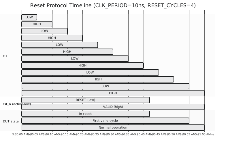
Figure 1 shows the release: rst_n rises 2 ns after the fourth edge at 40 ns, the flip-flops see it at 45 ns, and the first working cycle starts there with the whole design in its reset state.
A template
`timescale 1ns / 1ps

module tb_dut_template();

    parameter CLK_PERIOD   = 10;
    parameter RESET_CYCLES = 4;

    reg clk;
    reg rst_n;
    // other inputs as reg, outputs as wire

    initial clk = 0;
    always #(CLK_PERIOD/2) clk = ~clk;

    // your_dut dut (.clk(clk), .rst_n(rst_n), ...);

    initial begin
        $dumpfile("tb_dut_template.vcd");
        $dumpvars(0, tb_dut_template);

        rst_n = 1'b0;
        // other inputs to idle values

        repeat (RESET_CYCLES) @(posedge clk);
        #2;
        rst_n = 1'b1;

        @(posedge clk);

        $display("out of reset at %0t ns; starting tests", $time);

        // tests

        $display("done");
        $finish;
    end

endmodule
Production environments put this in a base test that every test inherits, so that a change in the required reset width is one edit. The next article is the rest of the start-up: every input to a known value, in order, so that no x gets loose.