Sampling the Outputs
Reading an output should be the easy half. The design computed it; look. But in an event-driven simulation when you look matters as much as what you look at, and several wrong moments look right. Sample at one of them and the testbench reports failures for a working design, which is the most demoralising kind of testbench bug there is.
The race
Section 5.1 covered this from the design side. A non-blocking assignment at a clock edge is scheduled, not applied: q <= d puts the update of q on a list, and the list is applied after every block active at that edge has run. So in the time step of the edge, a testbench block that also runs on posedge clk sees the old q:
// may print last cycle's value
always @(posedge clk_tb) begin
    $display("count = %0d", count_tb);
end
The testbench block and the design’s flip-flops are in the same active region; the update lands afterwards.
Two safe ways
Wait to the middle of the period. After the edge, half a period later, every update has landed and the next edge is far off:
localparam CLK_PERIOD = 10;

always @(posedge clk_tb) begin
    #(CLK_PERIOD/2);
    $display("[%0t] count = %0d", $time, count_tb);
end
Or use $strobe, which runs at the end of the time step, after all the updates, whenever in the step it was called:
always @(posedge clk_tb) begin
    $strobe("[%0t] count = %0d", $time, count_tb);
end
A trace
`timescale 1ns / 1ps

module tb_display_vs_strobe();
    reg       clk;
    reg [3:0] q;

    always @(posedge clk)
        q <= q + 1;

    initial begin
        clk = 0; q = 0;
        #1;

        repeat (4) begin
            @(posedge clk);
            $display("$display at the edge: q = %0d", q);
            $strobe ("$strobe at the edge:  q = %0d", q);
        end

        $finish;
    end

    always #5 clk = ~clk;
endmodule
$display at the edge: q = 0
$strobe at the edge:  q = 1
$display at the edge: q = 1
$strobe at the edge:  q = 2
$display at the edge: q = 2
$strobe at the edge:  q = 3
$display at the edge: q = 3
$strobe at the edge:  q = 4
Same time, different values: $display runs in the active region before the update, $strobe after it. Use $strobe to print the state of clocked logic at an edge and $display for progress messages in the stimulus.
The period
Figure 1 puts the zones together: drive just after the edge; the design updates; sample mid-period; leave the setup window before the next edge alone.
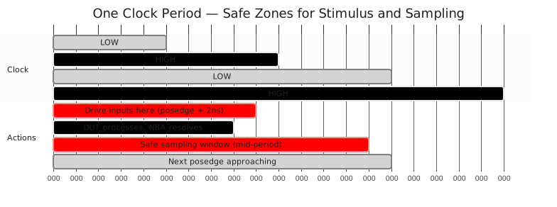
| Zone | When | Do |
|---|---|---|
| just after the edge | edge plus 1 to 2 ns | drive inputs |
| early in the period | edge plus 2 to 4 ns | the design settles |
| mid-period | half a period after the edge | sample outputs |
| before the next edge | last 2 ns | leave alone |
The adder, sampled
The adder is combinational and has no non-blocking updates to race, so waiting after driving is enough; $strobe costs nothing and keeps working if the design later grows registers:
`timescale 1ns / 1ps

module tb_adder_4bit_sampled();
    reg  [3:0] a_tb, b_tb;
    reg        cin_tb;
    wire [3:0] sum_tb;
    wire       cout_tb;

    adder_4bit dut (.a(a_tb), .b(b_tb), .cin(cin_tb), .sum(sum_tb), .cout(cout_tb));

    integer i, j;

    initial begin
        $dumpfile("tb_adder_4bit_sampled.vcd");
        $dumpvars(0, tb_adder_4bit_sampled);

        cin_tb = 0;

        for (i = 0; i < 4; i = i + 1) begin
            for (j = 0; j < 4; j = j + 1) begin
                a_tb = i[3:0];
                b_tb = j[3:0];
                #5;
                $strobe("  %0d + %0d = %0d (cout=%b)", a_tb, b_tb, sum_tb, cout_tb);
                #5;
            end
        end

        $finish;
    end
endmodule
The commonest cause of “the testbench says FAIL and the design is right” is a $display of a registered output in the same clocked block, with no delay. Half a period, or $strobe, and it goes away.
Driving and sampling are in place. The last piece turns a testbench that shows things into one that proves them: the self-checking loop.