Two Clocks
Real designs have more than one clock: a core at one rate, a memory interface at another, a slow peripheral at a third. The moment the testbench has two clocks it has a question people overlook: which clock drives which signals? Get it wrong and the simulation looks plausible and does not reflect what hardware would do.
Two generators
`timescale 1ns / 1ps

module tb_multi_domain();

    parameter SYS_CLK_PERIOD  = 10;    // 100 MHz
    parameter UART_CLK_PERIOD = 40;    // 25 MHz

    parameter SYS_RESET_CYCLES  = 4;
    parameter UART_RESET_CYCLES = 4;

    reg sys_clk  = 1'b0;
    reg uart_clk = 1'b0;

    reg sys_rst_n  = 1'b0;
    reg uart_rst_n = 1'b0;

    always #(SYS_CLK_PERIOD/2)  sys_clk  = ~sys_clk;
    always #(UART_CLK_PERIOD/2) uart_clk = ~uart_clk;
Two blocks, two parameters, no fixed relationship after time zero. A 4:1 ratio is tidy; a 100 MHz to 33.3 MHz ratio is not an integer and the clocks drift against each other, and the same patterns handle both.
The rule
A signal that feeds a flip-flop clocked by clk_a is driven in step with clk_a. One that feeds a clk_b flip-flop uses clk_b.
// right
@(posedge sys_clk); #2;
sys_data = 8'hA5;

@(posedge uart_clk); #2;
uart_tx_data = 8'h3C;

// wrong: a uart_clk-domain signal driven from sys_clk
@(posedge sys_clk); #2;
uart_tx_data = 8'h3C;
Driven from the wrong clock, the signal changes at some arbitrary point in the other domain’s cycle, and the relationship between the drive and the sample is different every run. Within a domain everything is referenced to that domain’s clock, as it is in hardware. The habit of driving everything from @(posedge clk) survives from single-clock testbenches and has to be broken when a second clock appears.
Two resets
Each domain has its own reset, released in step with its own clock. fork and join run the two sequences in parallel and wait for both:
    initial begin
        $dumpfile("tb_multi_domain.vcd");
        $dumpvars(0, tb_multi_domain);

        sys_rst_n  = 1'b0;
        uart_rst_n = 1'b0;

        fork
            begin
                repeat (SYS_RESET_CYCLES) @(posedge sys_clk);
                #2;
                sys_rst_n = 1'b1;
                $display("sys_rst_n released at %0t ns", $time);
            end

            begin
                repeat (UART_RESET_CYCLES) @(posedge uart_clk);
                #2;
                uart_rst_n = 1'b1;
                $display("uart_rst_n released at %0t ns", $time);
            end
        join

        @(posedge sys_clk);
        @(posedge sys_clk);

        $display("both domains ready at %0t ns", $time);
    end
The system reset releases at about 42 ns and the UART reset at about 162 ns, each on its own timeline, and the join is the point after which both are out of reset.
Crossing with a handshake
The system domain finishes something and raises done; the testbench then has to do something in the UART domain. Not with a delay:
// wrong: guesses the latency
#150;
@(posedge uart_clk); #2;
uart_rx_read = 1'b1;
With a condition, then a resynchronisation to the target clock:
@(posedge sys_clk); #2;
sys_start = 1'b1;
@(posedge sys_clk); #2;
sys_start = 1'b0;

wait (dut.sys_done);          // whenever it comes

@(posedge uart_clk);          // align to the UART clock before driving its signals
#2;
uart_rx_read = 1'b1;
@(posedge uart_clk); #2;
uart_rx_read = 1'b0;
wait on the event, then @(posedge) on the destination clock: that pair is the cross-domain idiom. The hierarchical reference dut.sys_done looks inside the design, which a testbench may do and hardware cannot.
A complete two-domain testbench
`timescale 1ns / 1ps

module tb_uart_bridge();

    parameter SYS_CLK_PERIOD    = 10;
    parameter UART_CLK_PERIOD   = 40;
    parameter SYS_RESET_CYCLES  = 4;
    parameter UART_RESET_CYCLES = 4;

    reg        sys_clk    = 1'b0;
    reg        uart_clk   = 1'b0;
    reg        sys_rst_n  = 1'b0;
    reg        uart_rst_n = 1'b0;

    reg [7:0]  sys_data_in = 8'h00;     // system domain
    reg        sys_valid   = 1'b0;

    reg        uart_rd_en  = 1'b0;      // UART domain

    wire [7:0] uart_data_out;
    wire       uart_data_valid;
    wire       sys_ready;

    always #(SYS_CLK_PERIOD/2)  sys_clk  = ~sys_clk;
    always #(UART_CLK_PERIOD/2) uart_clk = ~uart_clk;

    // uart_bridge dut (
    //     .sys_clk(sys_clk), .uart_clk(uart_clk), .sys_rst_n(sys_rst_n), .uart_rst_n(uart_rst_n),
    //     .sys_data_in(sys_data_in), .sys_valid(sys_valid), .uart_rd_en(uart_rd_en),
    //     .uart_data_out(uart_data_out), .uart_data_valid(uart_data_valid), .sys_ready(sys_ready)
    // );

    initial begin
        $dumpfile("tb_uart_bridge.vcd");
        $dumpvars(0, tb_uart_bridge);
    end

    initial begin
        sys_data_in = 8'h00;
        sys_valid   = 1'b0;
        uart_rd_en  = 1'b0;

        fork
            begin
                repeat (SYS_RESET_CYCLES) @(posedge sys_clk);
                #2;
                sys_rst_n = 1'b1;
            end
            begin
                repeat (UART_RESET_CYCLES) @(posedge uart_clk);
                #2;
                uart_rst_n = 1'b1;
            end
        join

        @(posedge sys_clk);
        @(posedge sys_clk);
        $display("[%0t ns] both domains initialised", $time);

        // send in the system domain
        @(posedge sys_clk); #2;
        sys_data_in = 8'hA5;
        sys_valid   = 1'b1;
        @(posedge sys_clk); #2;
        sys_valid   = 1'b0;

        // wait for it in the UART domain, then read there
        wait (uart_data_valid);
        @(posedge uart_clk); #2;
        uart_rd_en = 1'b1;
        @(posedge uart_clk); #2;
        uart_rd_en = 1'b0;

        $display("[%0t ns] UART data: %h (expected A5)", $time, uart_data_out);

        repeat (4) @(posedge uart_clk);
        $display("[%0t ns] done", $time);
        $finish;
    end

    initial begin
        #10000;
        $fatal(1, "TIMEOUT");
    end

endmodule
Every system-domain input is driven from sys_clk, every UART-domain input from uart_clk, the crossing is a wait and a resynchronisation, the resets run in parallel, and there is a watchdog. Figure 1 shows the handshake crossing the boundary: sys_valid two nanoseconds after a system edge, uart_data_valid appearing on a UART edge, the read driven on the next one.
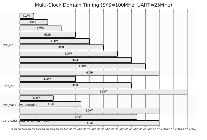
Three rules: generate each clock independently; drive each signal from its own domain’s clock; cross domains with a handshake, never a delay. All of this is the testbench side of clock domain crossing, and Module 7 does the hardware side, synchronisers and the Gray-coded FIFO.
With clocks, resets and initialisation in place, the next section is about making the testbench judge its own results.