The Four Parts of a Testbench
Every useful testbench, from a fifty-line gate check to a verification environment for a whole chip, has the same four parts. Not because a committee said so, but because that is what falls out when you ask what a testbench has to do. Knowing the shape before writing saves you from the commonest failure: one enormous initial block mixing driving, reading and printing, which works once and can never be extended or handed on.
The parts
- The instance of the design under test, wired to local signals.
- The stimulus, which drives the inputs over time.
- The checker, which samples the outputs and compares them with what was expected.
- The report, which says at the end how many checks ran and how many failed.
Each has one job (Figure 1). The stimulus does not judge; the checker does not drive; the report only counts. That is what lets you change the stimulus without touching the checker and tighten the checker without touching the stimulus.

No ports
module tb_adder_4bit();
endmodule
Empty parentheses. The testbench is the top of the hierarchy and nothing connects to it from above; it drives the design through internal signals. Adding ports out of habit compiles and does nothing useful.
reg and wire
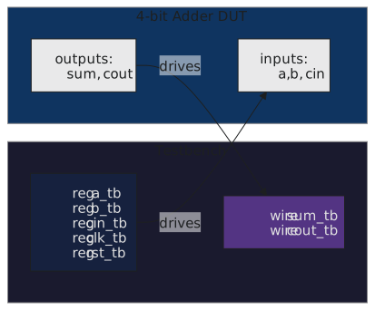
Inputs to the design are driven by the testbench’s procedural code, so they are reg on the testbench side. Outputs are driven by the design, so they are wire (Figure 2). That rule never varies. The one wrinkle is a bidirectional port, which is a wire in the testbench driven through a tri-state, and none of the designs in this section have one.
A skeleton
// adder_4bit.v
module adder_4bit (
    input  wire [3:0] a,
    input  wire [3:0] b,
    input  wire       cin,
    output wire [3:0] sum,
    output wire       cout
);
    assign {cout, sum} = a + b + cin;
endmodule
`timescale 1ns / 1ps

module tb_adder_4bit();

    // signals: inputs reg, outputs wire
    reg  [3:0] a_tb;
    reg  [3:0] b_tb;
    reg        cin_tb;
    wire [3:0] sum_tb;
    wire       cout_tb;

    // 1. the instance
    adder_4bit dut (
        .a   (a_tb),
        .b   (b_tb),
        .cin (cin_tb),
        .sum (sum_tb),
        .cout(cout_tb)
    );

    // 2. stimulus
    initial begin
        $dumpfile("tb_adder_4bit.vcd");
        $dumpvars(0, tb_adder_4bit);

        a_tb = 4'h0; b_tb = 4'h0; cin_tb = 1'b0; #10;
        a_tb = 4'h5; b_tb = 4'h3; cin_tb = 1'b0; #10;    // 8, no carry
        a_tb = 4'hF; b_tb = 4'h1; cin_tb = 1'b0; #10;    // 0, carry
        a_tb = 4'h7; b_tb = 4'h8; cin_tb = 1'b1; #10;    // 0, carry

        // 4. report
        $display("--- done ---");
        $finish;
    end

    // 3. observer; the checker comes later in the section
    always @(a_tb or b_tb or cin_tb) begin
        #1;
        $display("  %0d + %0d + %0d = %0d (cout=%b)", a_tb, b_tb, cin_tb, sum_tb, cout_tb);
    end

endmodule
iverilog -o sim_adder tb_adder_4bit.v adder_4bit.v
vvp sim_adder
Four lines of results, and you are still the checker. The fourth and fifth articles put the checker in the code. Even now, with the checker a stub, the four sections are in place, and adding to them later costs nothing. Note also the named port connections, .a(a_tb); a positional list silently miswires if the design’s port order ever changes, and a miswired test gives you false confidence, which is worse than no test.
The next article is about the stimulus: driving a combinational design is trivial, and driving a clocked one at the right moment relative to its clock is not.