Generating Clocks
In silicon the clock comes from a crystal or a PLL. In simulation nothing moves until the testbench moves it, and the clock is the first thing it has to make. The pattern is one you write once and reproduce from memory afterwards; the point of this article is to know why each line is there.
The pattern
parameter CLK_PERIOD = 10;    // ns, 100 MHz

reg clk;
initial clk = 0;
always #(CLK_PERIOD/2) clk = ~clk;
The period is a parameter, so that changing one number changes every timing calculation in the file: reset widths, offsets, watchdogs, anything written in terms of CLK_PERIOD.
The initial clk = 0 is not optional. An undriven reg starts as x, ~x is x, and a clock that starts unknown stays unknown forever; no flip-flop ever sees an edge and the whole design sits at x from the first nanosecond.
The always with no sensitivity list runs, waits half a period, toggles, and goes round again: a square wave with a 50 % duty cycle. Blocking assignment is right here; this is stimulus, not a flip-flop.
Fractional half-periods work if the timescale precision allows. With `timescale 1ns / 1ps a #3.5 is 3.5 ns; with `timescale 1ns / 1ns it rounds to 4.
The forever form
initial begin
    clk = 0;
    forever #(CLK_PERIOD/2) clk = ~clk;
end
The same thing. Use it when the clock should start late, with a delay before the loop, or stop after a count, with repeat in place of forever. Otherwise the always form is the default.
Other duty cycles
~clk gives 50 % because both phases get the same delay. For anything else, drive the two phases separately:
parameter CLK_PERIOD   = 20;    // 50 MHz
parameter CLK_HIGH_PCT = 25;

parameter CLK_HIGH = (CLK_PERIOD * CLK_HIGH_PCT) / 100;    // 5 ns
parameter CLK_LOW  = CLK_PERIOD - CLK_HIGH;                // 15 ns

reg clk;

always begin
    clk = 1;
    #(CLK_HIGH);
    clk = 0;
    #(CLK_LOW);
end
High for 5 ns, low for 15, a 25 % duty cycle. With more than one statement the always needs its begin and end.
Several clocks
One reg and one generator each:
parameter SYS_CLK_PERIOD  = 10;    // 100 MHz
parameter PERI_CLK_PERIOD = 40;    // 25 MHz

reg sys_clk, peri_clk;

initial sys_clk = 0;
always #(SYS_CLK_PERIOD/2) sys_clk = ~sys_clk;

initial peri_clk = 0;
always #(PERI_CLK_PERIOD/2) peri_clk = ~peri_clk;
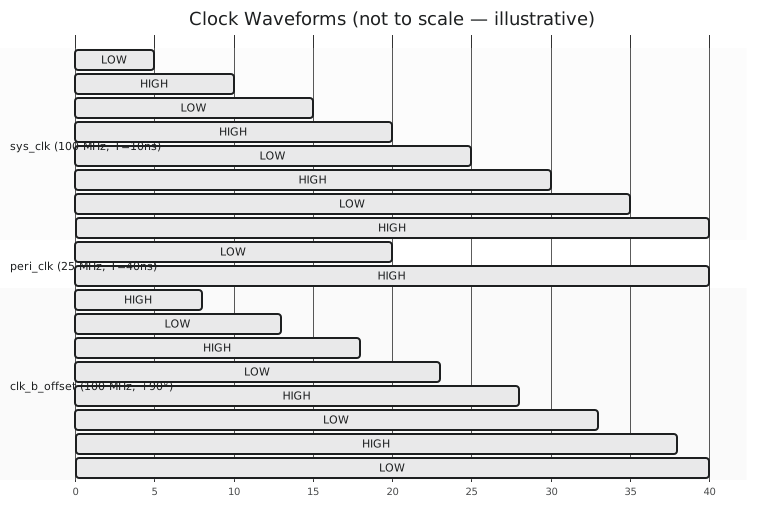
Both start low at time zero and rise at their own half periods, 5 ns and 20 ns, and thereafter run at their own rates.
A phase offset is a delayed first edge:
parameter CLK_A_PERIOD = 10;
parameter CLK_B_PERIOD = 10;

reg clk_a, clk_b;

initial clk_a = 0;
always #(CLK_A_PERIOD/2) clk_a = ~clk_a;

initial begin
    clk_b = 0;
    #(CLK_A_PERIOD/4);                    // a quarter period
    clk_b = 1;                            // first edge at 2.5 ns, clk_a's at 5
    forever #(CLK_B_PERIOD/2) clk_b = ~clk_b;
end
Figure 1 shows the two-frequency pair and the offset pair.
A skeleton
`timescale 1ns / 1ps

module tb_multi_clock();

    parameter SYS_CLK_PERIOD  = 10;
    parameter PERI_CLK_PERIOD = 40;

    reg sys_clk, peri_clk;

    initial sys_clk = 0;
    always #(SYS_CLK_PERIOD/2) sys_clk = ~sys_clk;

    initial peri_clk = 0;
    always #(PERI_CLK_PERIOD/2) peri_clk = ~peri_clk;

    initial begin
        $dumpfile("tb_multi_clock.vcd");
        $dumpvars(0, tb_multi_clock);
    end

    initial begin
        #200;
        $display("done at %0t ns", $time);
        $finish;
    end

endmodule
iverilog -o tb_multi_clock tb_multi_clock.v
vvp tb_multi_clock
gtkwave tb_multi_clock.vcd
Four system cycles per peripheral cycle, as the periods say. A parameterised period also lets you run the same testbench across the design’s whole frequency range by changing one constant.
With the clock running, the next article is reset: asserting it, holding it long enough, and releasing it without leaving the design metastable.