Driving the Inputs
Driving inputs looks like the easy part. Set some signals, wait. But drive too close to a clock edge and the testbench is racing the design’s flip-flops; drive with no plan and you get hundreds of lines of repeated stimulus nobody can check. The discipline is about the relationship between the stimulus and the design’s clock, and once you have it, it applies to every clocked design you test.
Combinational: drive and wait
For a design with no clock, drive the inputs, wait for the logic to settle, look at the output. A for loop over every input value is the cleanest form:
`timescale 1ns / 1ps

module tb_decoder_3to8();
    reg  [2:0] sel_tb;
    wire [7:0] out_tb;

    decoder_3to8 dut (.sel(sel_tb), .out(out_tb));

    integer i;

    initial begin
        $dumpfile("tb_decoder_3to8.vcd");
        $dumpvars(0, tb_decoder_3to8);

        for (i = 0; i < 8; i = i + 1) begin
            sel_tb = i[2:0];
            #10;
            $display("sel=%03b  out=%08b", sel_tb, out_tb);
        end

        $finish;
    end
endmodule
This scales: 16 inputs is 65 536 combinations and runs in well under a second. A testbench loop is a program loop and runs as many times as you like; it is not the unrolled hardware loop of section 5.4.
Clocked: drive after the edge
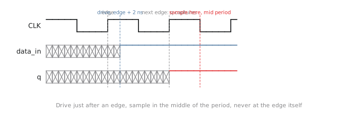
A flip-flop samples at the edge. Change its input at the same instant and you are racing its setup and hold. The rule is to drive a little after the edge, so the input is stable for the rest of the period:
@(posedge clk);     // wait for the edge
#2;                 // move 2 ns into the period
data_in = new_val;  // drive
By the next edge the input has been stable for nearly a whole period (Figure 1).
`timescale 1ns / 1ps

module tb_counter();
    reg        clk_tb;
    reg        rst_tb;
    reg        en_tb;
    wire [3:0] count_tb;

    localparam CLK_PERIOD  = 10;
    localparam CLK_TO_STIM = 2;     // drive this long after the edge

    counter_4bit dut (.clk(clk_tb), .rst(rst_tb), .en(en_tb), .count(count_tb));

    initial clk_tb = 0;
    always #(CLK_PERIOD/2) clk_tb = ~clk_tb;

    initial begin
        $dumpfile("tb_counter.vcd");
        $dumpvars(0, tb_counter);

        rst_tb = 1; en_tb = 0;
        @(posedge clk_tb); #CLK_TO_STIM;
        @(posedge clk_tb); #CLK_TO_STIM;
        rst_tb = 0;                          // two cycles of reset

        en_tb = 1;
        repeat (12) @(posedge clk_tb);       // count for 12
        #CLK_TO_STIM;

        en_tb = 0;                           // and hold
        repeat (3) @(posedge clk_tb);

        $finish;
    end
endmodule
The offset is a named parameter so that it is visible and adjustable; TCQ and TB_DLY are other common names. Besides avoiding the race, it models the clock-to-Q delay an upstream flip-flop would have, so the stimulus looks like real hardware.
Driving on the edge
// wrong
always #5 clk = ~clk;      // edges at 5, 15, 25 ...

initial begin
    data_in = 8'hAB;
    #5;
    data_in = 8'hCD;       // lands exactly on an edge; seen this cycle or next?
end
When a signal changes at the same time as the edge, the simulator may run the clock event first, so the flip-flop sees the old value, or the stimulus first, so it sees the new one. Different simulators, and different options of one simulator, choose differently. A testbench with this race passes on one tool and fails on another and the design is not at fault. Always @(posedge clk); #2;, never a bare delay that happens to land on an edge.
Tasks
When a sequence repeats, sending a byte, running a reset protocol, initialising a peripheral, put it in a task. A task can contain delays and event waits, unlike a function:
`timescale 1ns / 1ps

module tb_uart_tx();
    reg        clk_tb;
    reg        rst_tb;
    reg  [7:0] tx_data_tb;
    reg        tx_valid_tb;
    wire       tx_ready_tb;
    wire       tx_serial_tb;

    localparam CLK_PERIOD  = 10;
    localparam CLK_TO_STIM = 2;

    uart_tx dut (
        .clk      (clk_tb),
        .rst      (rst_tb),
        .tx_data  (tx_data_tb),
        .tx_valid (tx_valid_tb),
        .tx_ready (tx_ready_tb),
        .tx_serial(tx_serial_tb)
    );

    initial clk_tb = 0;
    always #(CLK_PERIOD/2) clk_tb = ~clk_tb;

    // wait for ready, present a byte, pulse valid for one cycle
    task send_byte;
        input [7:0] byte_val;
        begin
            @(posedge clk_tb);
            while (!tx_ready_tb) @(posedge clk_tb);
            #CLK_TO_STIM;

            tx_data_tb  = byte_val;
            tx_valid_tb = 1'b1;
            @(posedge clk_tb); #CLK_TO_STIM;

            tx_valid_tb = 1'b0;
            $display("[%0t] sent 0x%02h", $time, byte_val);
        end
    endtask

    initial begin
        $dumpfile("tb_uart_tx.vcd");
        $dumpvars(0, tb_uart_tx);

        rst_tb      = 1;
        tx_valid_tb = 0;
        tx_data_tb  = 8'h00;
        repeat (4) @(posedge clk_tb);
        #CLK_TO_STIM;
        rst_tb = 0;

        send_byte(8'h41);
        send_byte(8'h42);
        send_byte(8'h43);

        repeat (20) @(posedge clk_tb);
        $display("done");
        $finish;
    end
endmodule
The handshake lives in one place, the main block reads as three sends, and a change to the protocol is one edit. Tasks can also take expected values and check, which the last article of this section does.
The mirror image is next: reading outputs at the right moment, because sampling a flip-flop’s output in the same step it updates reports failures in a correct design.