Activity-Aware Design
Three articles, three techniques, three kinds of waste. Before the module closes it is worth having the decision explicit in one place, because a real power-constrained design almost always needs more than one of these working together, and picking the wrong one for a situation either leaves power on the table or spends area and complexity for no benefit.
The decision framework
| Question | If yes… | Technique |
|---|---|---|
| Is a block’s register bank idle for sustained periods, but the block needs to resume quickly? | Registers, sustained idle, fast resume needed | Clock gating (7.6.1) |
| Is an entire block unneeded for a long time, and can it tolerate a slower wake-up? | Whole block, long idle, slow wake-up acceptable | Power gating (7.6.2) |
| Is a purely combinational block’s result discarded on many cycles, while it keeps switching? | Combinational, result often unused, no register or power boundary | Operand isolation (7.6.3) |
| Does the idle block need its state to survive being powered down? | State must survive a sleep cycle | Retention registers, on top of power gating |
These are not mutually exclusive. A DSP accelerator might power-gate itself between jobs (with retention registers holding its configuration), clock-gate its register banks during short pipeline stalls within a job, and operand-isolate unused multiplier lanes on cycles where fewer channels are active than the hardware supports. Three techniques, three timescales of idleness, one block.
The power state machine
Coordinating several techniques in one block is a job for an FSM. It decides, cycle by cycle, which power mode the block should be in, based on activity signals and requests from the rest of the system:
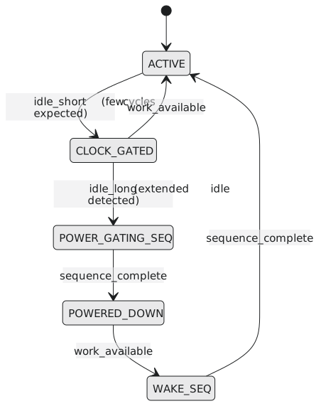
This is the same three-block, case-statement FSM structure from Section 5.6, applied to power states instead of a data-processing sequence. The POWER_GATING_SEQ and WAKE_SEQ states hold the ordered sequence from the power-gating article: save retained state, assert isolation, open the switch, and the reverse on the way back. Getting that order wrong is a documented class of chip bug, which is why it belongs in a carefully verified FSM rather than in control logic scattered across the design.
The cost of getting it wrong in either direction
Under-apply these techniques and you ship a design that burns more power than its competitors at the same performance, which is battery life in a phone or cooling and electricity at data-centre scale. Over-apply them, power-gating a block that wakes every few cycles or isolating a cheap gate that barely switches, and you have spent area and complexity on overhead that costs more than it saves, sometimes making the design slower or larger than the ungated version for no power benefit. Activity-aware design means matching each technique’s cost profile to the measured or carefully estimated activity of the block in question.
That measurement is not guesswork. Engineers run activity-annotated simulations (switching activity captured from realistic workloads, stored in SAIF or FSDB files) through a power analysis tool that reports estimated power block by block. Those reports are what justify, or rule out, applying one of these techniques to a particular block.
Looking back over Module 7
Section 7.1 made RTL reusable with parameters and structural generate. Section 7.2 made arithmetic correct at the edges, signed pitfalls and saturation, where correct in the common case is not good enough. Section 7.3 made that arithmetic fast enough to meet a clock through pipelining, including the stalls and bubbles a pipeline needs once it is not operating in isolation. Section 7.4 built the FIFO, and along the way Gray code, the one piece of number theory that lets multi-bit values move between clocks. Section 7.5 pulled clock domain crossing out as its own topic: quantified metastability, the two-flop synchronizer as a module, the handshake for arbitrary data, and the fact that none of it can be checked by simulation. Section 7.6 closed with the power side: three techniques, three kinds of idleness, and the judgement to know which fits.
Before moving on, check yourself against this list:
- Why parameterizing a module’s internals matters as much as parameterizing its ports
- When
generate if/generate caseearns its complexity over a plain parameter - Why mixing signed and unsigned operands silently makes the whole expression unsigned
- The same-sign-in, opposite-sign-out rule for signed overflow
- Why registering the carry, not only the operands, is what makes a split adder correct
- How to balance pipeline stages by delay rather than by component count
- The difference between a stall (freeze) and a bubble (invalidate one slot)
- Why a multi-bit binary value cannot be synchronized bit by bit, and how Gray code fixes it
- The extra-bit trick that separates FIFO full from empty
- Why MTBF improves exponentially, not linearly, with synchronizer stages
- When a handshake is the right tool instead of Gray code
- Why CDC bugs are invisible to RTL simulation by construction
- The ICG cell’s latch, and why a bare AND gate in a clock path is dangerous
- What isolation cells and retention registers each protect against
- When operand isolation’s own overhead costs more than it saves
Module 7 was about RTL that is correct, fast, safe across clock boundaries and power-conscious. In the next module we turn to the remaining piece: RTL that is also readable, synthesizes predictably, and can be debugged when something inevitably goes wrong.