Power Gating
The previous article stopped a block’s clock. This one cuts its power.
Clock gating saves power by stopping registers from switching, but every transistor in the block is still powered and still leaking a small current while it sits idle. At modern process nodes that leakage, the static power, can be a substantial fraction of the total budget, and clock gating does nothing about it because the transistors are still on, just not toggling. Power gating goes further and physically disconnects a block from its supply when the block is not needed.
The mechanism: a power switch
A power-gated block sits behind a large transistor called a header (if it switches the supply, VDD) or a footer (if it switches ground, VSS), controlled by a sleep signal:
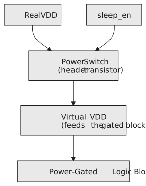
When sleep_en is asserted the switch opens, the block’s virtual VDD rail collapses, and the transistors inside stop leaking because there is no longer a voltage across them. This is an electrical disconnection, not a logical one, and it is the only technique in this section that addresses leakage rather than switching power.
Problem 1: floating outputs need isolation cells
The moment a block’s power collapses, its outputs do not settle to a clean 0 or 1. They float at some unpredictable voltage, because nothing is driving them. If those outputs feed still-powered logic elsewhere, that logic sees an undefined, possibly oscillating input, which can cause spurious switching, wrong evaluation, or in the worst case an unexpected current through a floating gate input.
The fix is an isolation cell, a simple gate (often an AND or OR) on every signal leaving a power-gated domain into an always-on domain, clamping the signal to a known value, usually 0, whenever the source domain is off:
// Conceptual description of what an isolation cell enforces.
// In practice these are inserted automatically by power-aware synthesis
// from a UPF power intent file, not written by hand as RTL.
assign isolated_output = power_domain_on ? raw_block_output : 1'b0;
Every signal leaving the domain needs one. Miss one and you have left one floating signal free to corrupt logic elsewhere the moment the domain powers down.
Problem 2: state is lost, unless you add retention
Powering a block down erases everything in its ordinary flip-flops; there is no voltage left to hold a state. For many blocks that is fine, if the block can start from scratch each time it wakes. Some blocks need to remember specific values across a sleep, a configuration register or a partially completed calculation, without re-initialising everything from outside on every wake-up.
Retention registers solve this with a small always-on shadow storage element, often a balloon latch on a small always-on rail, that saves the flop’s value just before power-down and restores it just after power-up:
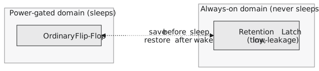
Retention registers cost area and some always-on leakage of their own, which is why they are used selectively, only for the state that needs to survive, rather than for every flop in the domain.
The full sequence, down and up
Getting the order wrong, by one step or one cycle, is a real source of chip-level bugs, which is why real designs drive it from a dedicated, carefully verified power-management state machine rather than ad hoc control logic:
- Stop feeding new work into the block (often with the clock gating from the previous article, applied first).
- Save any state that must survive into retention registers.
- Assert isolation on every output leaving the domain.
- Assert
sleep_en, opening the power switch and cutting the supply. - To wake: close the switch, wait for the supply to settle, release isolation, restore retained state, and only then resume feeding work.
All of this, power domains, isolation, retention and the sequencing between them, is specified separately from the RTL in a standard called UPF (Unified Power Format), or the closely related CPF. The chip’s power intent lives in those files, and power-aware synthesis and verification tools read them alongside the RTL to insert the isolation cells, retention cells and switches. You almost never hand-instantiate these primitives.
Practice Exercise
A power-gated video decoder feeds a single-bit “decode complete” flag directly into an always-on interrupt controller. Explain what goes wrong without an isolation cell, and what value the isolation cell should clamp the flag to while the decoder is off.
Solution
Without isolation, the moment the decoder powers down its “decode complete” output floats rather than settling to 0. The interrupt controller sampling that floating signal could read it as a spurious 1, raising an interrupt for a decode that never completed, or see it oscillate and raise several. The isolation cell should clamp the flag to 0 while the decoder domain is off, since a flag stuck at 0 correctly means “no new completion has occurred”, which is the safe thing for the controller to see from a block that is not running.
Power gating removes leakage that clock gating cannot, by disconnecting the supply rather than stopping the clock, but the disconnection brings two problems clock gating never had: floating outputs that need isolation cells, and lost state that needs retention registers. The sequence has to happen in strict order, driven by a power-management FSM and specified in UPF. In the next article we look at operand isolation, a much smaller-scale technique that stops wasted switching inside a block that is still fully powered and running.