Pipelining a Multiplier
In the previous article we split an adder. If an adder’s carry chain is sometimes long enough to need pipelining, a multiplier’s critical path is long enough that it usually does, at any width worth calling wide.
Recall Module 2: an N by N array multiplier’s critical path is $O(N)$ adder stages, and even a Wallace tree only brings the reduction down to $O(\log N)$ levels of carry-save adders plus one final carry-propagate add. At 32 or 64 bits that is still far more combinational depth than an adder of the same width, which is why the multiplier is usually the first thing a datapath pipelines.
Where to cut
Registering the inputs, multiplying combinationally and registering the output does not help: the multiply is still one large block between two registers. The cut has to go through the multiplier’s internal structure, at a point where a well-defined intermediate result exists.
For a hand-built Wallace tree, the natural cut is where Module 2 left off: after the carry-save tree has reduced the partial products to two rows, a sum row and a carry row, and before the final carry-propagate adder combines them. Both rows are the width of the product, so registering them costs two registers instead of one, and the second stage is “just” an adder that you already know how to pipeline further if needed.
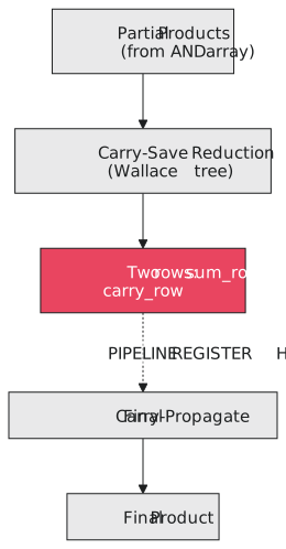
In behavioural RTL where the * operator stands in for the tree, the same idea can be expressed by splitting the multiplicand into halves. a * b is a * b[lo] + (a * b[hi] << N/2). Stage 1 computes the two narrower products, each with roughly half the depth of the full one; stage 2 adds them. The two partial products play the role of the sum and carry rows.
The 2-stage pipelined multiplier
`timescale 1ns / 1ps
`default_nettype none

module pipelined_mult #(parameter WIDTH = 16) (
    input  wire                      clk,
    input  wire [WIDTH-1:0]          a, b,
    input  wire                      valid_in,
    output reg  [2*WIDTH-1:0]        product,
    output reg                       valid_out
);
    localparam H = WIDTH / 2;

    // Stage 1: two half-width partial products. In a hand-built Wallace
    // tree these would be the sum row and carry row out of the reduction.
    reg [2*WIDTH-1:0] pp_lo, pp_hi;
    reg               valid_s1;

    always @(posedge clk) begin
        pp_lo    <= a * b[H-1:0];                 // a x lower half of b
        pp_hi    <= (a * b[WIDTH-1:H]) << H;      // a x upper half of b, shifted into place
        valid_s1 <= valid_in;
    end

    // Stage 2: final carry-propagate addition combining the two rows
    always @(posedge clk) begin
        product   <= pp_lo + pp_hi;
        valid_out <= valid_s1;
    end
endmodule
If you wire in your Module 2 tree instead, stage 1’s block captures the tree’s sum and carry rows directly and nothing else changes.
The valid signal is not optional
valid_in rides through the pipeline exactly like the carry in the previous article and the valid bits in Module 5. A multiplier usually sits inside a larger datapath that does not present a new operand pair every cycle; there are gaps and stalls. Without valid_out, downstream logic cannot tell the result of a multiply that happened two cycles ago from whatever was left in the pipeline register because nothing valid has flowed through yet.
Testbench: correctness and latency
module tb_pipelined_mult;
    parameter WIDTH = 8;
    reg clk = 0, valid_in;
    reg [WIDTH-1:0] a, b;
    wire [2*WIDTH-1:0] product;
    wire valid_out;

    pipelined_mult #(.WIDTH(WIDTH)) dut (
        .clk(clk), .a(a), .b(b), .valid_in(valid_in),
        .product(product), .valid_out(valid_out)
    );

    always #5 clk = ~clk;

    initial begin
        $dumpfile("tb.vcd");
        $dumpvars(0, tb_pipelined_mult);

        valid_in = 0; a = 0; b = 0;
        @(negedge clk);

        a = 8'd13; b = 8'd11; valid_in = 1;   // 13 * 11 = 143
        @(negedge clk);   // cycle 1: partial products captured
        valid_in = 0;
        @(negedge clk);   // cycle 2: product should now be valid

        if (product == 16'd143 && valid_out == 1'b1)
            $display("PASS: product=%0d arrived on cycle 2 with valid_out asserted", product);
        else
            $display("FAIL: product=%0d valid_out=%b (expected 143, 1)", product, valid_out);

        $finish;
    end
endmodule
As with the adder, the test is not only “is the number right” but “does it show up on the cycle the pipeline depth predicts, with valid_out set”.
FPGA vendors build their hard multiplier blocks (Xilinx DSP48, Intel DSP blocks) with optional pipeline registers at exactly these internal boundaries. When a synthesis tool infers a multiplier from * and sees a register on the output, it will usually map the whole thing onto one of those blocks rather than build it from general logic.
Practice Exercise
Extend the multiplier to 3 stages by pipelining the final adder with the split from the previous article, so a 16-bit multiply takes 3 cycles: one for the partial products, two for the split final addition. Confirm the valid signal threads through all three stages.
Solution
module pipelined_mult_3stage #(parameter WIDTH = 16) (
    input  wire               clk,
    input  wire [WIDTH-1:0]   a, b,
    input  wire               valid_in,
    output reg  [2*WIDTH-1:0] product,
    output reg                valid_out
);
    localparam H = WIDTH / 2;
    reg [2*WIDTH-1:0] pp_lo, pp_hi;
    reg               valid_s1;

    // Stage 1: partial products
    always @(posedge clk) begin
        pp_lo    <= a * b[H-1:0];
        pp_hi    <= (a * b[WIDTH-1:H]) << H;
        valid_s1 <= valid_in;
    end

    // Stage 2: lower half of the final add, capture the carry (same pattern as 07-02/03)
    reg [WIDTH-1:0]       sum_lo;
    reg                   carry_mid;
    reg [2*WIDTH-1:WIDTH] pp_lo_hi, pp_hi_hi;
    reg                   valid_s2;

    always @(posedge clk) begin
        {carry_mid, sum_lo} <= pp_lo[WIDTH-1:0] + pp_hi[WIDTH-1:0];
        pp_lo_hi <= pp_lo[2*WIDTH-1:WIDTH];
        pp_hi_hi <= pp_hi[2*WIDTH-1:WIDTH];
        valid_s2 <= valid_s1;
    end

    // Stage 3: upper half of the final add, using the registered carry
    always @(posedge clk) begin
        product[WIDTH-1:0]       <= sum_lo;
        product[2*WIDTH-1:WIDTH] <= pp_lo_hi + pp_hi_hi + carry_mid;
        valid_out <= valid_s2;
    end
endmodule
valid_in now passes through three registers, valid_s1, valid_s2 and valid_out, one per stage, mirroring the data. A testbench that applies an input on cycle 0 should see valid_out and the correct product on cycle 3, not before and not after.
A multiplier’s path is long enough, even after a Wallace reduction, that pipelining it is the expectation rather than an optimisation. The place to cut is between the reduction and the final add, and the valid bit threading through every stage is the only way downstream logic can tell a result from a register that has not seen valid data yet. That closes Section 7.2. In the next article, Section 7.3 generalises pipelining properly: how many stages, where to cut a whole datapath, and what to do when it has to stop.