Balancing an N-Stage Pipeline
Section 7.2 pipelined an adder and a multiplier by finding one natural cut in one structure. Real datapaths are rarely one operator. They are an adder feeding a multiplier feeding a comparator feeding a mux, and the question becomes how many cuts, and where, across the whole chain.
The formula, generalised
From Module 5: once a pipeline is full, throughput is $1/T_{clk}$ and latency is $N \times T_{clk}$ for $N$ stages. What decides $N$ is the target clock period against the total combinational delay you are trying to fit:
$$N_{stages} = \left\lceil \frac{T_{combinational,total}}{T_{clk,target}} \right\rceil$$
Say the full datapath (multiply, add, compare) has 4 ns of combinational delay end to end and the target period is 1.2 ns (about 833 MHz). $\lceil 4 / 1.2 \rceil = 4$ stages, minimum. The word minimum matters: the formula gives the fewest stages that could work if the delay were split perfectly evenly. Whether you can split it evenly is the harder problem.
Balance the delay, not the operator count
The mistake that undermines many first pipelines is splitting a three-operator chain into three stages, one operator each, because that is where the boundaries already are. If the multiply takes 2.5 ns, the add 0.8 ns and the compare 0.7 ns, one operator per stage gives a 2.5 ns stage next to two short ones. The clock is set by the slowest stage, so the two fast stages buy nothing.
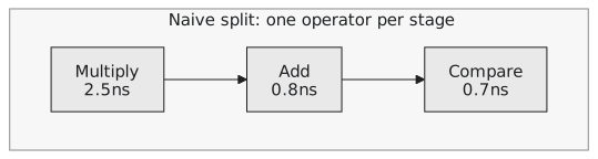
$$T_{clk} \geq \max(2.5, 0.8, 0.7) = 2.5\text{ ns}$$
The fix is to balance delay across the stages you need, which sometimes means splitting one slow operator across two stages (as we did with the multiplier) while merging two fast ones into a single stage:
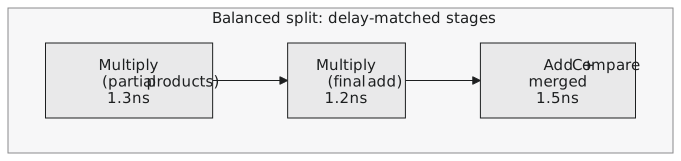
$$T_{clk} \geq \max(1.3, 1.2, 1.5) = 1.5\text{ ns}$$
Same stage count, same total work, a clock nearly 40 percent faster, from paying attention to where the delay actually is rather than where the module boundaries happen to be.
More stages is not free
It is tempting to conclude that more stages is always better. Two costs push back. Every register you add costs area and power, even when it only passes a value through, and every stage also needs its valid bit threaded through as we did in Section 7.2. More important for correctness, more stages means more latency, and in a design with feedback (a loop where a result feeds an earlier stage, common in control systems and iterative algorithms) extra latency can be a functional problem, not a cosmetic one. A control loop with too many stages in it can become unstable or too slow to react no matter how fast the clock runs.
There is also a floor. Register setup and hold times and clock-to-Q delay (Module 3) do not shrink however thinly you slice the logic between them. Past a point you are adding registers that cost area and power while the achievable period stays pinned by flip-flop overhead. The right question is not how deep can this be pipelined, but what is the shallowest pipeline that meets the target frequency. Every stage past that is latency and area with nothing in return.
Practice Exercise
A datapath has three combinational blocks in series with delays 3.2 ns, 1.1 ns and 1.4 ns. The target clock period is 1.8 ns. Find the minimum number of stages and propose a split that balances delay as evenly as possible.
Solution
Total combinational delay: $3.2 + 1.1 + 1.4 = 5.7$ ns. Minimum stages: $\lceil 5.7 / 1.8 \rceil = 4$, since $5.7/1.8 \approx 3.17$.
A per-block split gives 3 stages with the 3.2 ns block on its own, which already violates the target since $3.2 > 1.8$. That block has to be split internally into at least two pieces; assume it splits evenly into two 1.6 ns halves.
Merging blocks B and C into one stage gives $1.1 + 1.4 = 2.5$ ns, also too slow. So they stay separate. Final split: 1.6 ns, 1.6 ns, 1.1 ns, 1.4 ns. The worst stage is 1.6 ns, under the 1.8 ns target, using exactly the 4 stages the formula predicted.
The formula gives the minimum stage count for a target period; hitting it in practice means balancing actual delay across the stages, splitting slow operators and merging fast ones, rather than cutting where the modules happen to end. In the next article we cover the mechanics of inserting a pipeline stage into an existing combinational block without changing what it computes.