Getting Started with Icarus Verilog and GTKWave
Icarus Verilog is one of the most popular open-source Verilog simulators, widely used for learning digital design and verifying HDL code. Combined with GTKWave, a waveform viewer, it provides a complete simulation environment. In this tutorial, we’ll install both tools and create a simple multiplexer design to demonstrate the workflow.
Icarus Verilog (often called iverilog) is a compiler that translates Verilog source code into executable programs for simulation. It supports most of the IEEE-1364 Verilog standard and is perfect for educational purposes and small to medium-sized designs.
GTKWave is a fully featured waveform viewer that can display VCD (Value Change Dump) files generated during simulation.
Installing Icarus Verilog
Icarus Verilog is available in most Linux package managers and can also be built from source for the latest features.
Ubuntu/Debian Installation
The easiest way to install Icarus Verilog is through apt:
sudo apt update
sudo apt install -y iverilog
Verify Installation
Check that Icarus Verilog is installed correctly:
iverilog -v
You should see version information and compilation details.
Building from Source (Optional)
For the latest version, you can build from source:
# Install dependencies
sudo apt install -y autoconf gperf flex bison

# Clone repository
git clone https://github.com/steveicarus/iverilog.git
cd iverilog

# Build and install
sh autoconf.sh
./configure
make
sudo make install
Refer to official documentation for detailed steps on compiling from source.
Installing GTKWave
GTKWave is the standard waveform viewer for viewing VCD files generated by Verilog simulations.
Ubuntu/Debian Installation
sudo apt install -y gtkwave
Verify Installation
gtkwave --version
macOS Installation
If you’re on macOS, use Homebrew:
brew install gtkwave
Windows Installation
For Windows users, download the installer from the GTKWave website.
Creating a Multiplexer Design
Let’s create a 4:1 multiplexer in Verilog to demonstrate the simulation workflow.
Create Project Directory
mkdir -p ~/designs
cd ~/designs
Create the Multiplexer Design (mux4to1.v)
Create a file named mux4to1.v:
// mux4to1.v - 4:1 Multiplexer
module mux4to1 (
    input  wire [1:0] sel,     // 2-bit select signal
    input  wire [7:0] in0,     // Input 0 (8-bit)
    input  wire [7:0] in1,     // Input 1 (8-bit)
    input  wire [7:0] in2,     // Input 2 (8-bit)
    input  wire [7:0] in3,     // Input 3 (8-bit)
    output reg  [7:0] out      // Output (8-bit)
);

    always @(*) begin
        case (sel)
            2'b00: out = in0;
            2'b01: out = in1;
            2'b10: out = in2;
            2'b11: out = in3;
            default: out = 8'h00;
        endcase
    end

endmodule
Create the Testbench (tb_mux4to1.v)
Create a file named tb_mux4to1.v:
// tb_mux4to1.v - Testbench for 4:1 Multiplexer
`timescale 1ns/1ps

module tb_mux4to1;
    // Testbench signals
    reg  [1:0] sel;
    reg  [7:0] in0, in1, in2, in3;
    wire [7:0] out;

    // Instantiate the multiplexer (Device Under Test)
    mux4to1 dut (
        .sel(sel),
        .in0(in0),
        .in1(in1),
        .in2(in2),
        .in3(in3),
        .out(out)
    );

    // Clock for time reference
    reg clk = 0;
    always #5 clk = ~clk;  // 10ns period (100MHz)

    // Test stimulus
    initial begin
        // Initialize VCD dump for waveform viewing
        $dumpfile("mux4to1.vcd");
        $dumpvars(0, tb_mux4to1);

        // Display header
        $display("Time\tsel\tin0\tin1\tin2\tin3\tout");
        $display("================================================");

        // Initialize inputs
        sel = 2'b00;
        in0 = 8'hAA;
        in1 = 8'hBB;
        in2 = 8'hCC;
        in3 = 8'hDD;

        // Test Case 1: Select input 0
        #10;
        sel = 2'b00;
        #10;
        $display("%0t\t%b\t%h\t%h\t%h\t%h\t%h", $time, sel, in0, in1, in2, in3, out);

        // Test Case 2: Select input 1
        sel = 2'b01;
        #10;
        $display("%0t\t%b\t%h\t%h\t%h\t%h\t%h", $time, sel, in0, in1, in2, in3, out);

        // Test Case 3: Select input 2
        sel = 2'b10;
        #10;
        $display("%0t\t%b\t%h\t%h\t%h\t%h\t%h", $time, sel, in0, in1, in2, in3, out);

        // Test Case 4: Select input 3
        sel = 2'b11;
        #10;
        $display("%0t\t%b\t%h\t%h\t%h\t%h\t%h", $time, sel, in0, in1, in2, in3, out);

        // Test Case 5: Change inputs while selecting
        in0 = 8'h11;
        in1 = 8'h22;
        in2 = 8'h33;
        in3 = 8'h44;

        sel = 2'b00;
        #10;
        $display("%0t\t%b\t%h\t%h\t%h\t%h\t%h", $time, sel, in0, in1, in2, in3, out);

        sel = 2'b01;
        #10;
        $display("%0t\t%b\t%h\t%h\t%h\t%h\t%h", $time, sel, in0, in1, in2, in3, out);

        sel = 2'b10;
        #10;
        $display("%0t\t%b\t%h\t%h\t%h\t%h\t%h", $time, sel, in0, in1, in2, in3, out);

        sel = 2'b11;
        #10;
        $display("%0t\t%b\t%h\t%h\t%h\t%h\t%h", $time, sel, in0, in1, in2, in3, out);

        // Test Case 6: Rapid switching
        repeat (8) begin
            sel = $random % 4;
            #10;
            $display("%0t\t%b\t%h\t%h\t%h\t%h\t%h", $time, sel, in0, in1, in2, in3, out);
        end

        // Finish simulation
        $display("================================================");
        $display("Simulation completed successfully!");
        #10;
        $finish;
    end

    // Timeout watchdog
    initial begin
        #1000;
        $display("ERROR: Simulation timeout!");
        $finish;
    end

endmodule
Compiling and Running the Simulation
Compile with Icarus Verilog
Use the iverilog command to compile your design and testbench:
iverilog -o mux4to1.vvp tb_mux4to1.v mux4to1.v
Command breakdown:
-o mux4to1.vvp: Output file name (compiled simulation)tb_mux4to1.v: Testbench filemux4to1.v: Design file
This creates a mux4to1.vvp file, which is the compiled simulation executable.
Run the Simulation
Execute the simulation using vvp (Verilog VVP simulator):
vvp mux4to1.vvp
You should see output similar to:
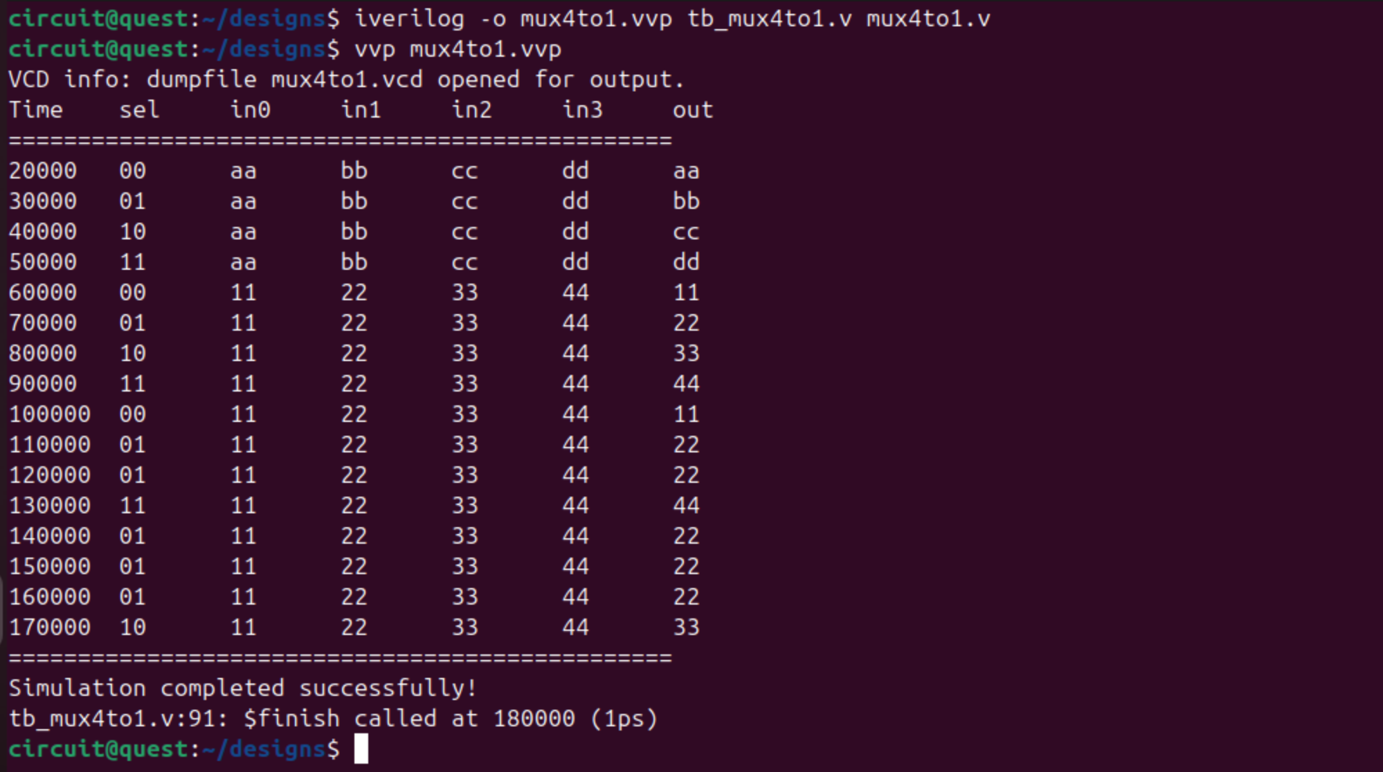
The simulation also generates a mux4to1.vcd file containing waveform data.
Viewing Waveforms with GTKWave
Now let’s visualize the simulation results:
gtkwave mux4to1.vcd
GTKWave will open with your waveform data. Signals can be added from the left pane.

Adding Signals to the Waveform View
- In the SST (Signal Search Tree) window on the left, you’ll see the hierarchy
- Click on
tb_mux4to1to expand it - Select the signals you want to view:
selin0,in1,in2,in3out
- Click Append or drag them to the Signals window
Alternatively, you can use surfer for viewing the waveforms. Follow this guide on installation and usage of Surfer.
GTKWave Navigation Tips
- Zoom In/Out: Use the magnifying glass buttons or mouse wheel
- Zoom Fit: Click the “Zoom Fit” button to see the entire simulation
- Time Cursor: Click on the waveform to place a cursor
- Measure Time: Right-click and drag to measure time intervals
- Change Radix: Right-click on a signal → Data Format → choose Hex, Binary, or Decimal
- Search: Click on a signal and press Ctrl+F to search for specific values
What to Observe
In the waveforms, you should see:
- The
selsignal cycling through 00, 01, 10, 11 - The
outsignal following the selected input (in0,in1,in2, orin3) - Immediate changes in output when select or input values change (combinational logic)
Advanced Features
Adding Timing Checks
You can add timing checks to your testbench:
initial begin
    // Check setup time
    $setuphold(posedge clk, sel, 1, 0.5);
end
Generating Detailed Output
Use the -v flag with iverilog for verbose output:
iverilog -v -o mux4to1.vvp tb_mux4to1.v mux4to1.v
Using System Tasks
Icarus Verilog supports many system tasks:
$display("Message");       // Print to console
$monitor("var=%d", var);   // Monitor variable changes
$time;                     // Current simulation time
$random;                   // Generate random numbers
$readmemh("file.hex", mem); // Load memory from file
Troubleshooting
Compilation Errors
If you get syntax errors:
# Check for common issues
iverilog -t null -Wall tb_mux4to1.v mux4to1.v
No VCD File Generated
Ensure your testbench has:
$dumpfile("filename.vcd");
$dumpvars(0, module_name);
GTKWave Shows No Signals
- Make sure the VCD file is not empty
- Check that
$dumpvarswas called before any signal changes - Try loading signals manually from the hierarchy
Simulation Hangs
- Add a timeout watchdog in your testbench
- Check for missing
$finishstatement - Look for infinite loops in your design